Variable capacity vane pump with dual control chambers

a vane pump and variable capacity technology, applied in machines/engines, liquid fuel engines, positive displacement liquid engines, etc., can solve the problems of waste of energy pumping surplus, unneeded working fluid, etc., to reduce the volumetric capacity of the pump, reduce the reaction force, and alter the pump capacity

Active Publication Date: 2010-09-14
HANON SYST EFP CANADA LTD
View PDF14 Cites 42 Cited by
  • Summary
  • Abstract
  • Description
  • Claims
  • Application Information

AI Technical Summary

Benefits of technology

[0012]According to a second aspect of the present invention, there is provided a variable capacity vane pump comprising: a pump casing having a pump chamber therein; a vane pump rotor rotatably mounted in the pump chamber; a pump control ring enclosing the vane pump rotor within said pump chamber, the control pump ring being moveable about a pivot pin within the pump chamber to alter the capacity of the pump; a control chamber defined between the pump casing, the pump control ring, the pivot pin and a resilient seal between the pump control ring and the pump casing, the control chamber being operable to receive pressurized fluid to create a force to move the pump control ring to reduce the volumetric capacity of the pump; and a return spring acting between pump ring and the casing to bias the pump ring towards a position of maximum volumetric capacity, the return spring acting against the force of the control chamber to establish an equilibrium pressure and wherein the pivot pin and the resilient seal are positioned to reduce the area of the pump control ring within the control chamber such that the resulting force on the pump control ring exerted by pressurized fluid in the control chamber is reduced.
[0013]Preferably, the return spring is oriented such that the biasing force it applies to the pump control ring farmer reduces the reaction forces on the pivot pin. Also preferably, the control chamber is positioned, with respect to the pivot pin, such that the resulting force reduces reaction forces on the pivot pin.

Problems solved by technology

Thus, at lower speeds, the pump will be operating at a higher capacity than necessary for those speeds, wasting energy pumping the surplus, unnecessary, working fluid.

Method used


Image

  • Variable capacity vane pump with dual control chambers
  • Variable capacity vane pump with dual control chambers
  • Variable capacity vane pump with dual control chambers

Examples


Embodiment Construction

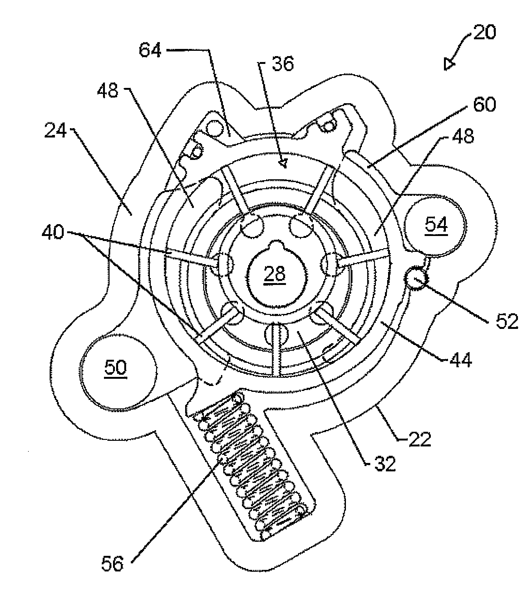
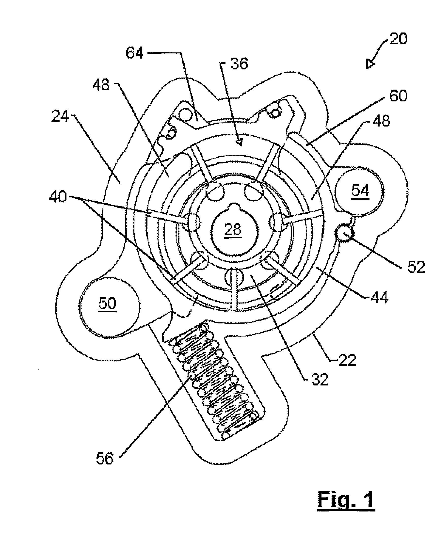
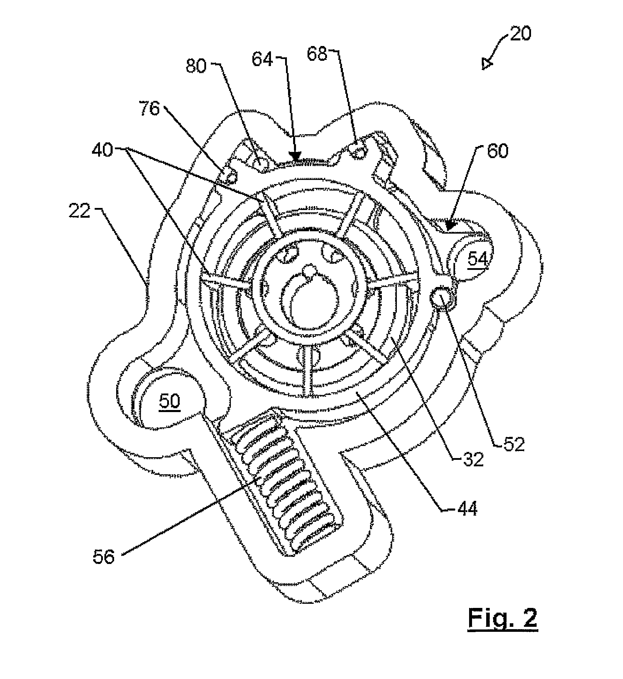
[0020]A variable capacity vane pump in accordance with an embodiment of the present invention is indicated generally at 20 in FIGS. 1, 2 and 3.

[0021]Referring now to FIGS. 1, 2 and 3, pump 20 includes a housing or casing 22 with a front face 24 which is sealed with a pump cover (not shown) and a suitable gasket, to an engine (not shown) or the like for which pump 20 is to supply pressurized working fluid.

[0022]Pump 20 includes a drive shaft 28 which is driven by any suitable means, such as the engine or other mechanism to which the pump is to supply working fluid, to operate pump 20. As drive shaft 28 is rotated, a pump rotor 32 located within a pump chamber 36 is turned with drive shaft 28. A series of slidable pump vanes 40 rotate with rotor 32, the outer end of each vane 40 engaging the inner surface of a pump control ring 44, which forms the outer wall of pump chamber 36. Pump chamber 36 is divided into a series of working fluid chambers 48, defined by the inner surface of pump ...


PUM


Abstract

A variable capacity vane pump includes a pump casing having a pump chamber with an inlet and an outlet port. A pump control ring is moveable within the pump chamber to alter the capacity of the pump. A vane pump rotor is rotatably mounted within the pump control ring and includes a plurality of slidably mounted vanes engaging the inside surface of the pump control ring. First and second control chambers between the pump casing and the pump control ring are operable to receive pressurized fluid to urge the pump control ring to reduce the volumetric capacity of the pump. A return spring biases the pump ring toward a position of maximum volumetric capacity against the force of the first and second control chambers to establish an equilibrium pressure. The supply of pressurized fluid to the second control chamber may be varied to change the equilibrium pressure of the pump.

Description

CROSS-REFERENCE TO RELATED APPLICATIONS[0001]This application is the national phase under 35 U.S.C. §371 of PCT International Application No. PCT / CA05 / 01946 which has an international filing date of Dec. 21, 2005, which designated the United States of America, which application claims the benefit of U.S. Provisional Application No. 60 / 639,185 filed on Dec. 22, 2004. The entire disclosure of each of the above applications is incorporated herein by reference.FIELD OF THE INVENTION[0002]The present invention relates to a variable capacity vane pump. More specifically, the present invention relates to a variable capacity vane pump in which at least two different equilibrium pressures can be selected between by supplying working fluid to two or more control chambers adjacent the control ring.BACKGROUND OF THE INVENTION[0003]Variable capacity vane pumps are well known and can include a capacity adjusting element, in the form of a pump control ring that can be moved to alter the rotor ecce...

Claims


Application Information

Patent Timeline
Patent Type & Authority Patents(United States)
IPC IPC(8): F04C2/00F04C14/18
CPCF04C2/04F04C14/226F04C2/344F04C14/18
Inventor WILLIAMSON, MATTHEWSHULVER, DAVID R.
Owner HANON SYST EFP CANADA LTD
Why Eureka
Try Eureka