Lens barrel

a technology of lens barrel and barrel body, which is applied in the field of lens barrel, can solve the problems of reducing the size of the lens barrel, and achieve the effect of improving the quality of the lens barrel

Active Publication Date: 2010-09-14
PANASONIC CORP
View PDF18 Cites 14 Cited by
  • Summary
  • Abstract
  • Description
  • Claims
  • Application Information

AI Technical Summary

Benefits of technology

[0011]With this lens barrel, since the blocking drive motor and the element drive motor are disposed flanking the second optical axis when viewed in a direction along the second optical axis, the optical path blocking unit is longer in one direction, but the length is shorter in the other direction of the optical path blocking unit. This affords a more compact lens barrel.

Problems solved by technology

However, depending on how these drive motors are disposed, they may hinder efforts to reduce the size of the lens barrel.

Method used


Image

  • Lens barrel
  • Lens barrel
  • Lens barrel

Examples


Embodiment Construction

[0038]Selected embodiments of the present invention will now be explained with reference to the drawings. It will be apparent to those skilled in the art from this disclosure that the following descriptions of the embodiments of the present invention are provided for illustration only and not for the purpose of limiting the invention as defined by the appended claims and their equivalents.

[0039]Overview of Digital Camera

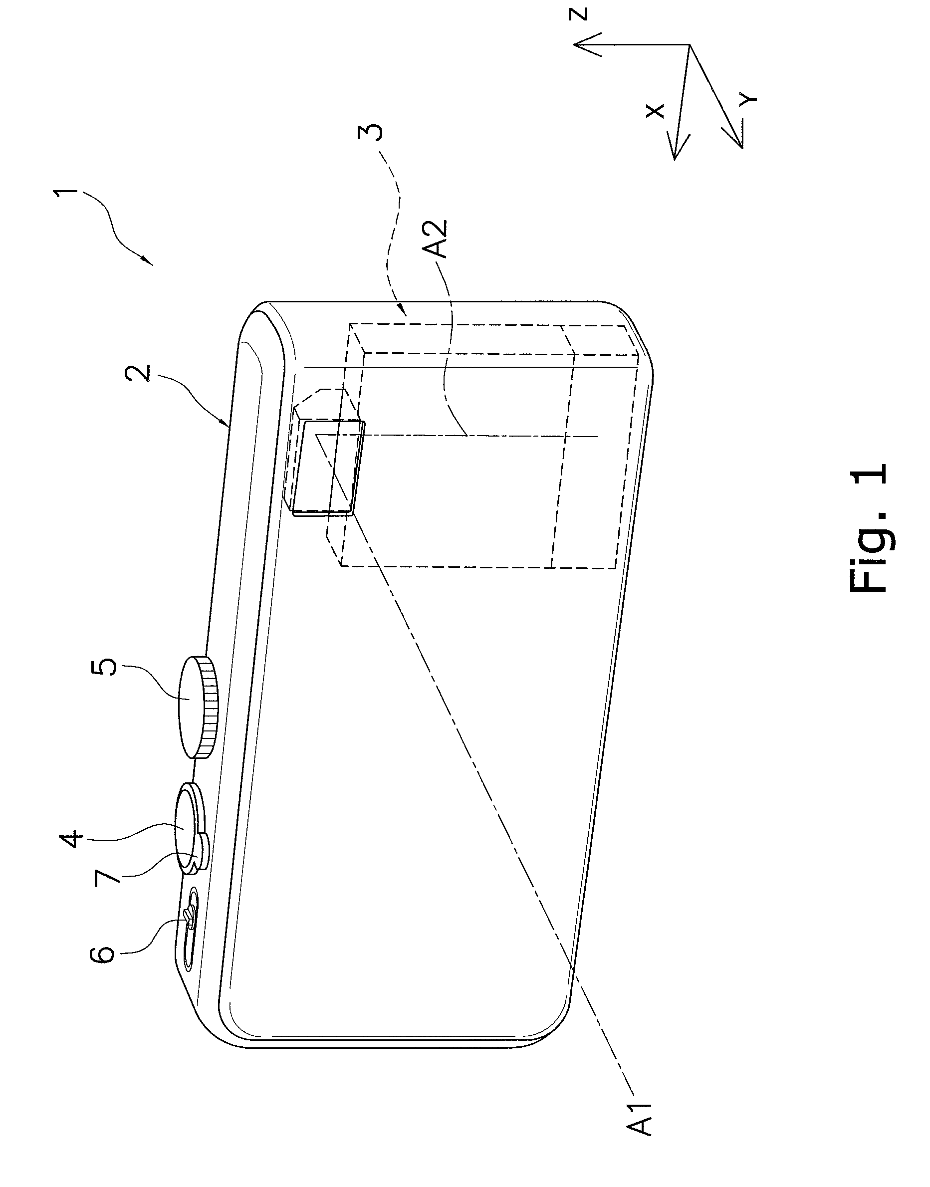
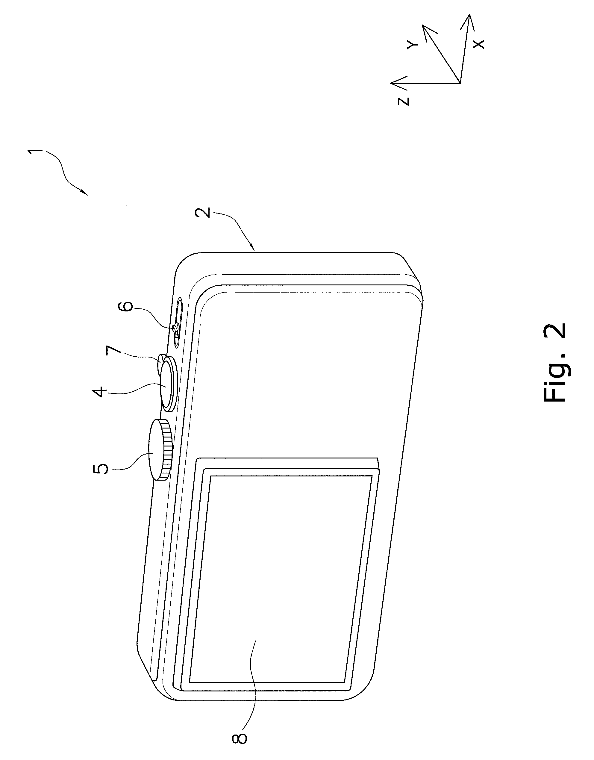
[0040]A digital camera 1 according to an embodiment of the present invention will now be described through reference to FIGS. 1 and 2. FIGS. 1 and 2 are simplified perspective views of the digital camera 1.

[0041]The digital camera 1 is a camera for capturing an image of a subject, and employs a bending optical system for boosting magnification and reducing the overall size.

[0042]In the following description, the six sides of the digital camera 1 are defined as follows.

[0043]The side facing the subject when an image is being captured by the digital camera 1 is called ...


PUM


Abstract

A lens barrel has a first lens group, a second lens group, a third lens group, a first support frame for supporting the first lens group, a second support frame for supporting the second lens group, a first driving unit, a shutter unit, and an aperture unit. The first lens group has an overall negative refractive power, and includes a prism. The second support frame is driven along a second optical axis by the first driving unit. The shutter unit has a shutter mechanism, a shutter drive motor configured to drive the shutter mechanism, a neutral density filter, and a filter drive motor configured to drive the neutral density filter. The shutter drive motor and the filter drive motor are disposed flanking the second optical axis when viewed in a direction along the second optical axis.

Description

CROSS-REFERENCE TO RELATED APPLICATIONS[0001]This application claims priority to Japanese Patent Application No. 2007-340583 filed on Dec. 28, 2007. The entire disclosure of Japanese Patent Application No. 2007-340583 is hereby incorporated herein by reference.BACKGROUND[0002]1. Technical Field[0003]The technical field relates to a lens barrel having a bending optical system.[0004]2. Description of the Related Art[0005]Digital cameras that make use of imaging elements have become very popular in recent years. With digital camera, there has been a need not only for a greater number of pixels in the imaging elements, but also for higher performance of the lens barrel, which forms an optical image on the imaging elements. More specifically, there is a need for a lens barrel equipped with a higher-power zoom lens system.[0006]In the field of digital cameras, the overall size of the camera needs to be reduced in order to make it more portable. Accordingly, there has been a need for a mor...

Claims


Application Information

Patent Timeline
Patent Type & Authority Patents(United States)
IPC IPC(8): G02B15/14
CPCG02B7/021G02B7/023G02B7/026G03B17/17
Inventor ITO, DAISUKE
Owner PANASONIC CORP
Why Eureka
Try Eureka