Developing roller and method of producing the roller, process cartridge, and electrophotographic image-forming apparatus

a technology of electrophotographic image and process cartridge, which is applied in the direction of manufacturing tools, portable power-driven tools, instruments, etc., can solve the problems of fog in an image, and inability to produce high-quality electrophotographic images. to achieve the effect of stably providing high-quality electrophotographic images

Active Publication Date: 2010-09-21
CANON KK
View PDF20 Cites 42 Cited by
  • Summary
  • Abstract
  • Description
  • Claims
  • Application Information

AI Technical Summary

Benefits of technology

[0014]Further, the present invention is directed to providing an electrophotographic image-forming apparatus capable of stably outputting high-quality electrophotographic images and a process cartridge to be used in the apparatus.
[0020]According to a further aspect of the present invention, there is provided a developing roller capable of solving the above problems (1) and (2) at high levels. In addition, according to the present invention, there are provided a process cartridge and an electrophotographic image-forming apparatus each of which is capable of stably providing high-quality electrophotographic images under a variety of environments.

Problems solved by technology

When the surface of the developing roller has poor toughness, the surface of the developing roller is shaved upon long-term use of the developing roller, with the result that an image failure occurs in some cases.
In addition, the filming may cause fog in an image.
As a result, a stripe-like defect called banding often occurs in the electrophotographic image.

Method used


Image

  • Developing roller and method of producing the roller, process cartridge, and electrophotographic image-forming apparatus
  • Developing roller and method of producing the roller, process cartridge, and electrophotographic image-forming apparatus
  • Developing roller and method of producing the roller, process cartridge, and electrophotographic image-forming apparatus

Examples


example 1

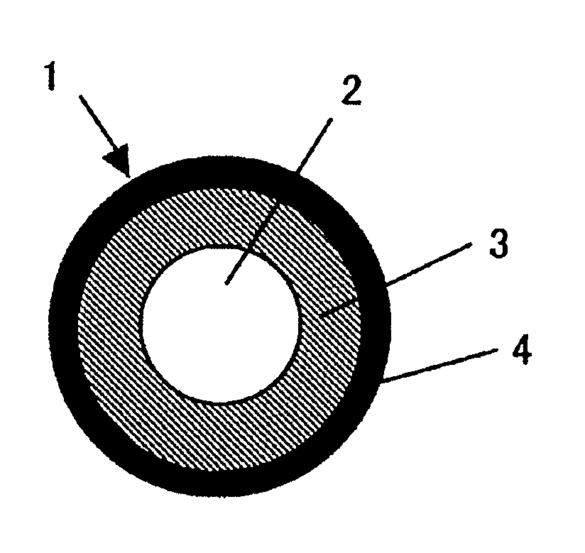
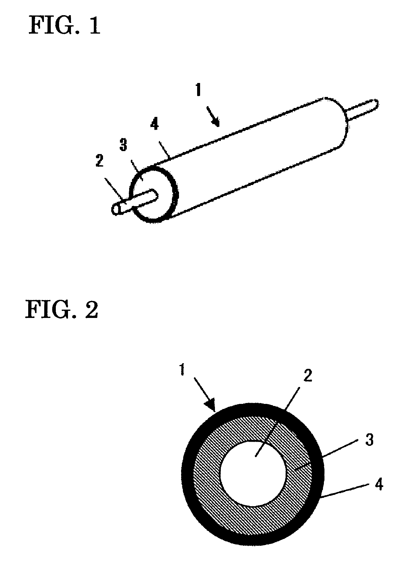
Preparation of Conductive Mandrel 2

[0125]The conductive mandrel 2 was prepared by: applying a primer (trade name: DY35-051; manufactured by Dow Corning Toray Silicone Co., Ltd.) to a core metal having a diameter of 6 mm made of SUS304; and baking the applied primer at a temperature of 150° C. for 30 minutes.

[0126]3>

[0127]Next, the conductive mandrel 2 was placed in a die, and a liquid, conductive, silicone rubber (product manufactured by Dow Corning Toray Silicone Co., Ltd. and having an ASKER-C hardness of 40 degrees and a volume resistivity of 1×10⁵ Ω·cm) was injected into a cavity formed in the die. Subsequently, the die was heated, and the silicone rubber was vulcanized at 150° C. for 15 minutes. The resultant was removed from the die, and was then heated at 200° C. for 2 hours so that a curing reaction might be completed. Thus, the resin layer 3 having a diameter of 12 mm was provided on the outer periphery of the conductive mandrel 2.

[0128]4>

[0129]The following materials were ...

examples 2 to 32

[0132]Developing rollers were each prepared in the same manner as in Example 1 except that the formulation of the paint for forming a surface layer in Example 1 was changed as shown in Tables 2 and 3 below.

example 33

[0133]A developing roller was prepared in the same manner as in Example 1 except that the formulation of the paint for forming a surface layer in Example 1 was changed as shown below. The following materials were mixed and stirred with a stirring motor. The mixture was dissolved in MEK so that the total solid content might be 30 mass %, and then the contents were mixed. After that, the resultant was subjected to uniform dispersion with a sand mill, whereby the paint 1 for forming a surface layer was obtained.

[0134]

Diol Compound A:56 parts by mass (as a solid)Diol Compound Z: 6 parts by mass (as a solid)Isocyanate Compound P:38 parts by mass (as a solid)Carbon black (trade name: MA100;25 parts by massmanufactured by MitsubishiChemical Corporation):Resin particles (trade name:30 parts by massART PEARL C600 transparent;manufactured by NegamiChemical Industrial Co., Ltd.):


PUM

PropertyMeasurementUnit
RHaaaaaaaaaa
temperatureaaaaaaaaaa
RHaaaaaaaaaa

Abstract

The present invention intends to provide a method of producing a developing roller capable of providing high-quality electrophotographic images under a variety of environments. The method of producing a developing roller according to the present invention is a method of producing a developing roller having a mandrel, a resin layer on the outer periphery of the mandrel, and a surface layer on the outer periphery of the resin layer, the method including the step of curing a mixture containing a carbon black, a specific diol, and a specific isocyanate compound to form the surface layer.

Description

CROSS-REFERENCE TO RELATED APPLICATIONS[0001]This application is a continuation of International Application No. PCT / JP2009 / 059476, filed May 18, 2009, which claims the benefit of Japanese Patent Application No. 2008-143175, filed May 30, 2008.BACKGROUND OF THE INVENTION[0002]1. Field of the Invention[0003]The present invention relates to a developing roller for use in an electrophotographic image-forming apparatus adopting an electrophotographic mode such as a copying machine, a printer, or the receiving apparatus of a facsimile, and a method of producing the roller.[0004]In addition, the present invention relates to a process cartridge and an electrophotographic image-forming apparatus each of which uses the developing roller.[0005]2. Description of the Related Art[0006]A contact developing method has been known as a method of developing an image in an electrophotographic apparatus. In the contact developing method, an electrostatic latent image formed on a photosensitive drum is ...

Claims


Application Information

Patent Timeline
Patent Type & Authority Patents(United States)
IPC IPC(8): B21K1/02G03G15/08F16C13/00B05C1/08
CPCG03G15/0818Y10T29/49885Y10T29/49563
Inventor NAKAMURA, MINORUTAKAYAMA, YOSHIYUKINAGAOKA, KAZUAKIYAMADA, MASAKI
Owner CANON KK
Why Eureka
Try Eureka