Apparatus and methods for creation of down hole annular barrier

a technology of annular barrier and apparatus, which is applied in the direction of survey, borehole/well accessories, construction, etc., can solve the problems of not preventing fluid migration, reducing the flow velocity of gas, and affecting the efficiency of cementing operations, so as to reduce the tendency of gas to flow. the effect of increasing the flow velocity

Inactive Publication Date: 2010-09-21
WEATHERFORD TECH HLDG LLC
View PDF205 Cites 83 Cited by
  • Summary
  • Abstract
  • Description
  • Claims
  • Application Information

AI Technical Summary

Benefits of technology

[0026]In another embodiment, a casing or liner string includes a stage tool, a folded unexpanded expandable portion, and a ball seat shoe. After positioning the expandable portion at the desired location, a ball is place into the string and subsequently locates in the ball seat. When located in the ball seat, the ball seals the interior of the string and prevents fluid from flowing out of the string. Sufficient pressure is applied to unfold the expandable portion and press the elastomeric seals against the wellbore wall. After expansion, additional pressure is applied to break a rupturable disk in the stage tool for fluid communication with the annulus. Cement is pumped down the casing string and out into the annulus. The closing plug behind the cement lands on the stage tool, thereby closing fluid communication with the annulus. After the cement sets, a drill string can be lowered to drill out the stage tool and the ball seat shoe and drill ahead to form the next wellbore section.
[0030]In another embodiment, the casing or liner string having at least one expandable portion may be used to restrict an inner diameter of a wellbore. Sometimes, it may be desirable to restrict the inner diameter such that the flow velocity may be increased. For example, in a gas well, an increase in flow may keep the head of the water from killing the well. In such instances, the string may be positioned inside the wellbore and thereafter expanded into sealing engagement with the wellbore. In this manner, the expanded string may restrict the inner diameter of the wellbore.
[0031]In another embodiment, the casing or liner string having at least one expandable portion may be used to insulate a wellbore. For example, insulation may be desired to keep the production near the reservoir temperature, thereby reducing the tendency of the gas to form condensate that may kill the well. In such instances, the string may be positioned inside the wellbore and thereafter expanded into sealing engagement with the wellbore. The additional layer of tubular may provide insulation to the well.

Problems solved by technology

Initially a hole is drilled in the earth to a depth at which earth cave-in or wellbore fluid control become potential issues.
While the casing may structurally prevent cave-in, it will not prevent fluid migration along a length of the well in the annulus.
Unfortunately, cementing operations require cessation of drilling operations for considerable periods of time.
During the cementing operations drilling rig costs and other fixed costs still accrue yet no drilling progress is made.
Regardless of whether or not the cross-section is initially circular or is folded, expandable pipe has limitations of expandability based on the expansion mechanism chosen.
If the chosen expansion mechanism is miscalculated in a given circumstance, the result can be extremely disadvantageous.
In such a situation, the expanded pipe is not useful as a barrier and further, because the pipe has been expanded or partially expanded, retrieval may be impractical.
Remedying such a situation consumes valuable rig time and accrues other costs associated with remediation equipment and replacement of the failed expandable pipe.

Method used


Image

  • Apparatus and methods for creation of down hole annular barrier
  • Apparatus and methods for creation of down hole annular barrier
  • Apparatus and methods for creation of down hole annular barrier

Examples


Embodiment Construction

[0049]The invention generally relates to methods and apparatus for creating an annular barrier about a casing shoe.

[0050]Expandable Barrier

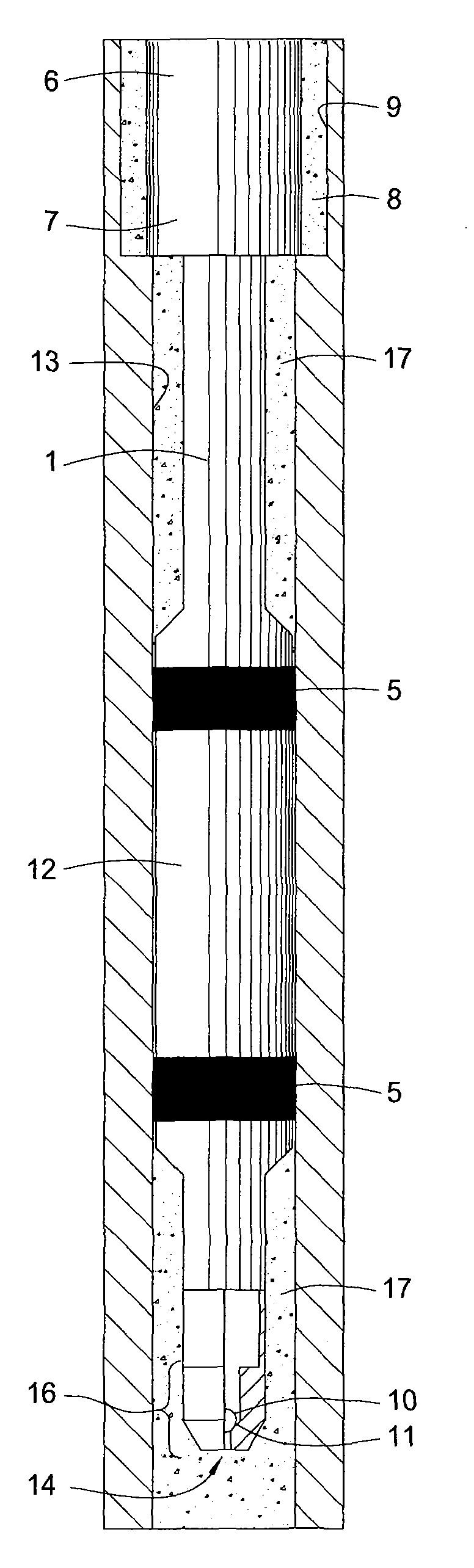
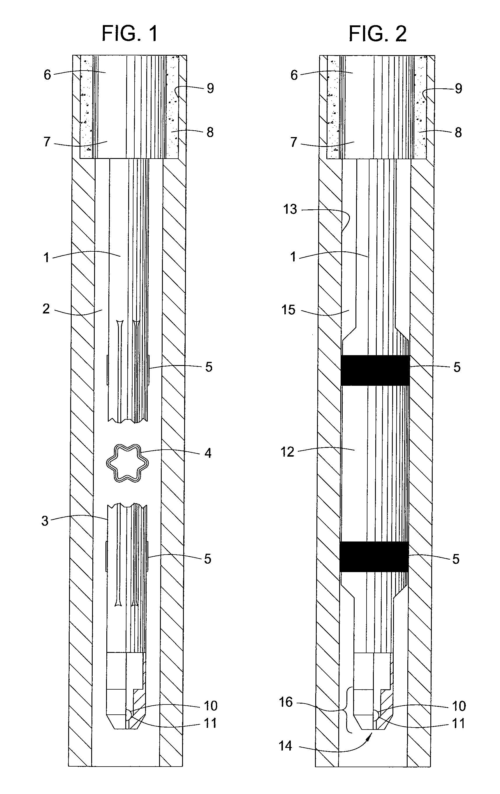
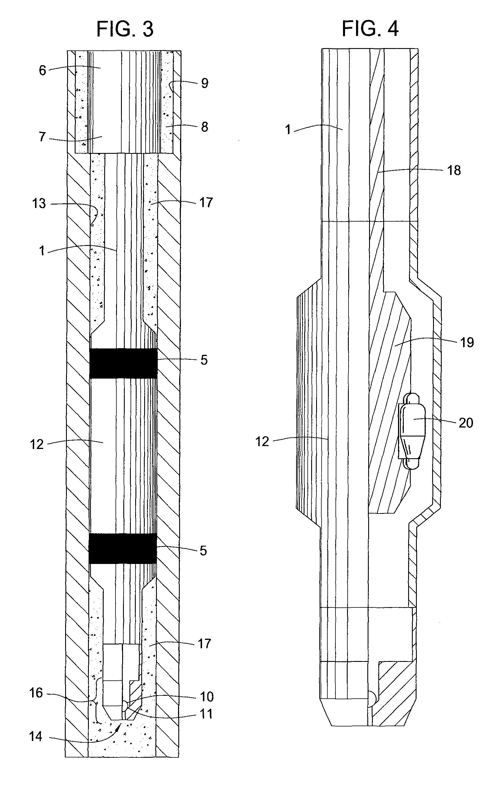
[0051]The embodiments of FIGS. 1, 2 and 3 are shown deployed beneath a previously and conventionally installed casing 6 in a previously drilled wellbore 9. The annular barrier between the conventional shoe portion 7 of the previously installed casing 6 and the previously drilled wellbore 9 is only cement 8.

[0052]FIG. 1 shows a casing string 1 deployed in a sectioned wellbore 2 where the casing string 1 includes an unexpanded folded expandable portion 3 and a cross-section thereof 4 and having two elastomeric coated regions 5 about a perimeter of the folded portion 3. The wellbore 2 is drilled after testing of the barrier formed by the cement 8. The casing string 1 is lowered from the surface into the wellbore 2. A ball 10 is placed in the interior of the casing 1 and allowed to seat in a ball seat 11, thereby plugging the lower end of the casing ...


PUM


Abstract

Methods and apparatus are provided for performing an expedited shoe test using an expandable casing portion as an annular fluid barrier. Further provided are methods and apparatus for successfully recovering from a failed expansion so that a shoe test can be completed without replacement of the expandable casing portion. In one recovery method, a selectively actuatable fluid circulation tool is provided to further expand the expandable portion or perform a cementing operation. Additionally, methods and apparatus are provided to drill a wellbore and form an annular fluid barrier in a single trip.

Description

CROSS-REFERENCE TO RELATED APPLICATION[0001]This application claims benefit of U.S. Provisional Patent Application Ser. No. 60 / 705,857, filed on Aug. 5, 2005, which application is incorporated herein by reference in its entirety.BACKGROUND OF THE INVENTION[0002]1. Field of the Invention[0003]Embodiments of the invention generally relate to methods and apparatus for creating an annular barrier in a wellbore. More particularly, embodiments of the invention relates to methods and apparatus for isolating at least a portion of a wellbore from at least another portion of the wellbore.[0004]2. Description of the Related Art[0005]As part of the wellbore construction process, a hole or wellbore is typically drilled into the earth and then lined with a casing or liner. Sections of casing or liner are threaded together or otherwise connected as they are run into the wellbore to form what is referred to as a “string.” Such casing typically comprises a steel tubular good or “pipe” having an oute...

Claims


Application Information

Patent Timeline
Patent Type & Authority Patents(United States)
IPC IPC(8): E21B33/13
CPCE21B33/1208E21B33/14E21B43/103E21B47/1025E21B47/117E21B43/105
Inventor GIROUX, RICHARD LEERING, LEV
Owner WEATHERFORD TECH HLDG LLC
Why Eureka
Try Eureka