
Cutting balloon having sheathed incising elements

a cutting balloon and incising element technology, applied in the field of medical devices, can solve the problems of fragile inflation balloon, affecting the safety of patients, and affecting the safety of patients, and not necessarily protecting the relatively fragile balloon

Active Publication Date: 2010-09-21
BOSTON SCI SCIMED INC
View PDF48 Cites 39 Cited by
  • Summary
  • Abstract
  • Description
  • Claims
  • Application Information

AI Technical Summary

Benefits of technology

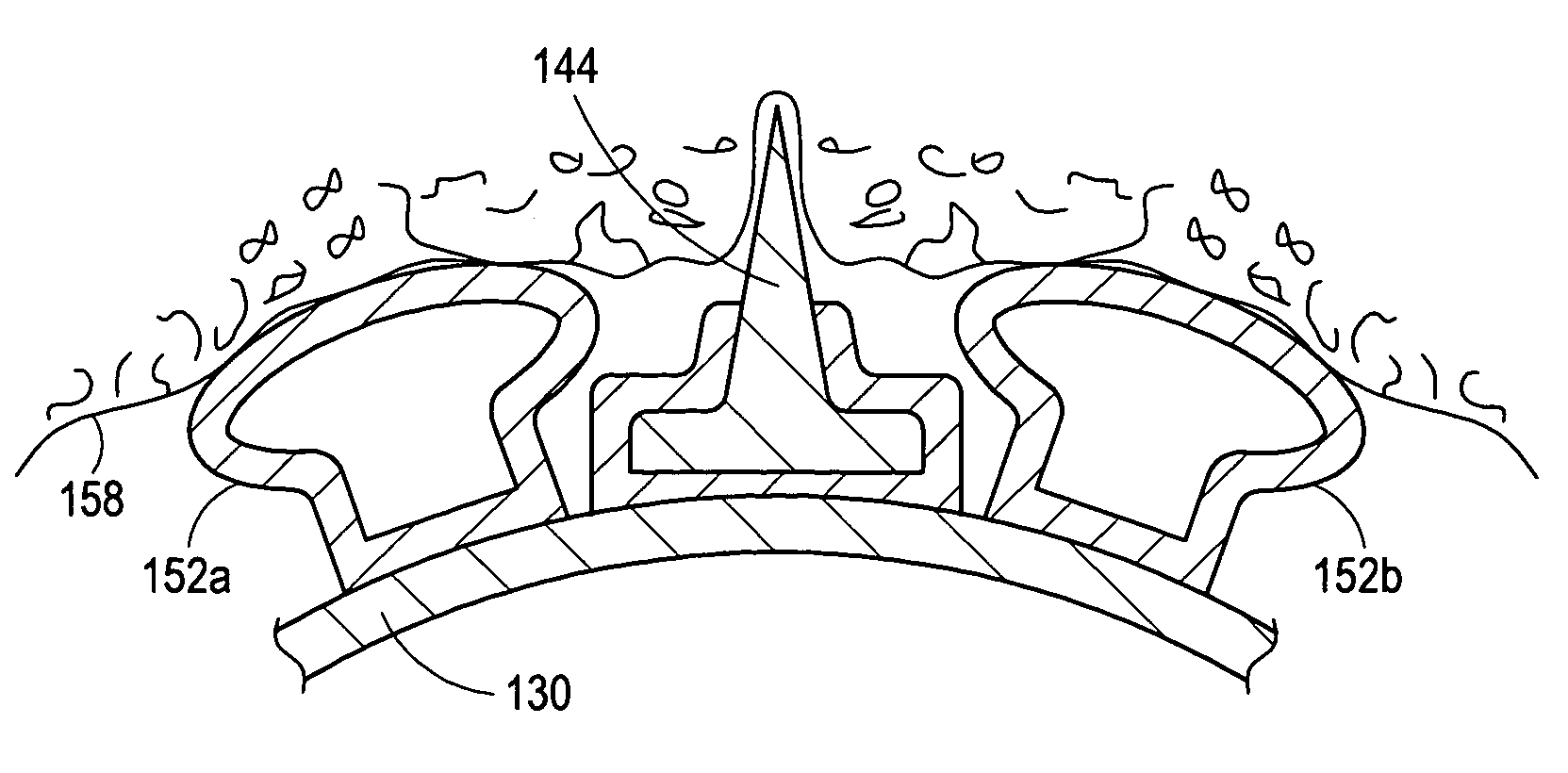
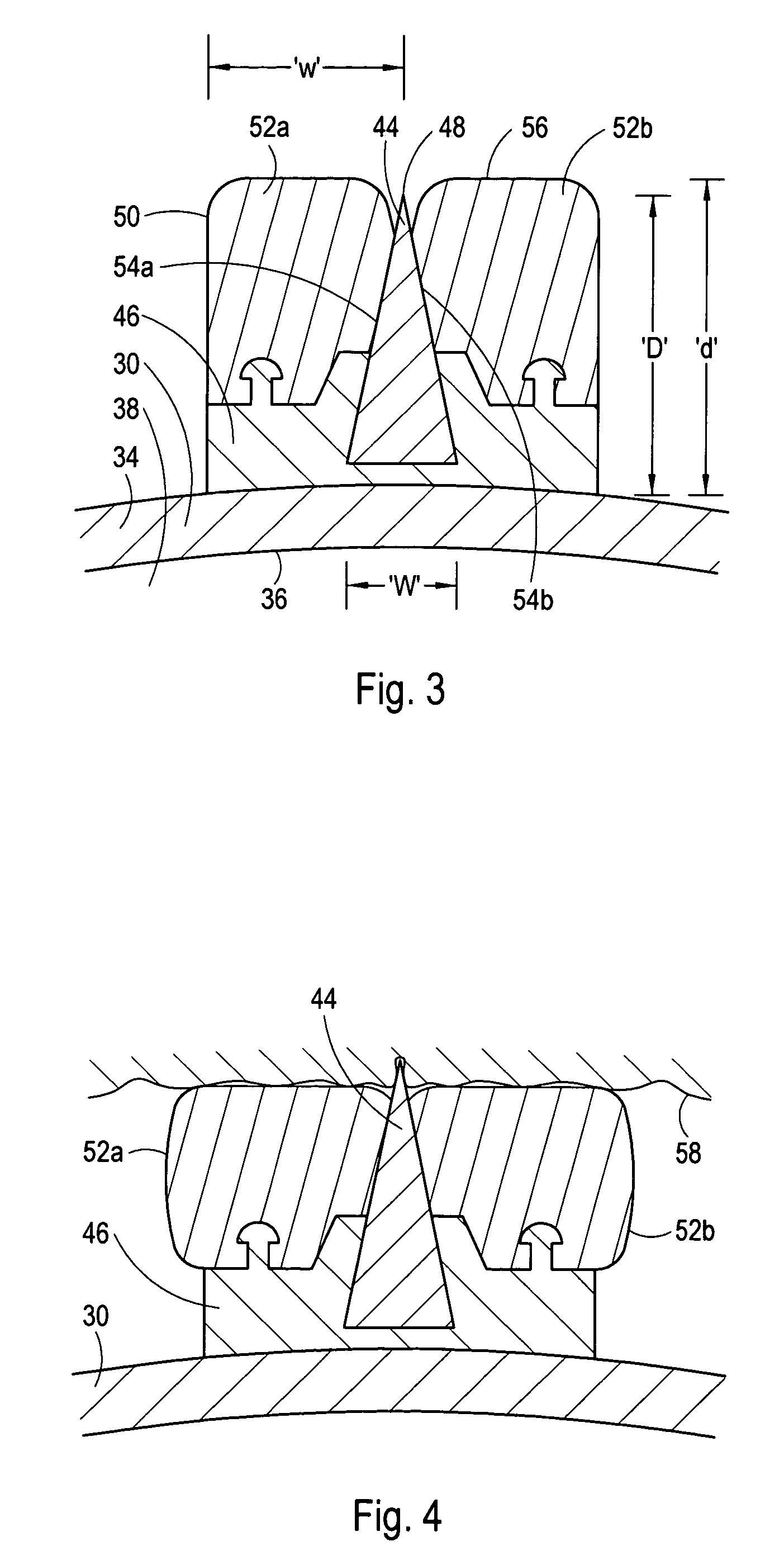
[0009]Each sheath member extends radially from the mounting pad and terminates at a sheath member surface that is located farther from the longitudinal axis than the operative surface feature of the corresponding incising element. With this cooperation of structure, the sheath member(s) makes first contact with the tissue during a balloon inflation. Once contact has been established between the tissue and the sheath members, further inflation of the inflatable balloon causes the sheath member(s) to radially compress, and in some cases deflect, between the tissue and the inflatable balloon exposing the operative surface feature of the incising element for tissue incision. In one aspect of the present invention, the sheath members can be configured to selectively limit the amount of incising element that is exposed, and as a consequence, control the incision depth.

Problems solved by technology

In the absence of suitable precautions, the incising elements can tear, cut or perforate the thin, fragile inflation balloon during assembly of the cutting balloon, handling or during clinical use.
In a worst case, a balloon perforation or tear can result in an unsuccessful PTCA atherectomy procedure and the loss of inflation fluid into the patient's vasculature.
However, the clover leaf design disclosed by Shiber does not necessarily protect the relatively fragile balloon during installation of the parting edges on the clover leaf balloon.

Method used


Image

  • Cutting balloon having sheathed incising elements
  • Cutting balloon having sheathed incising elements
  • Cutting balloon having sheathed incising elements

Examples


Embodiment Construction

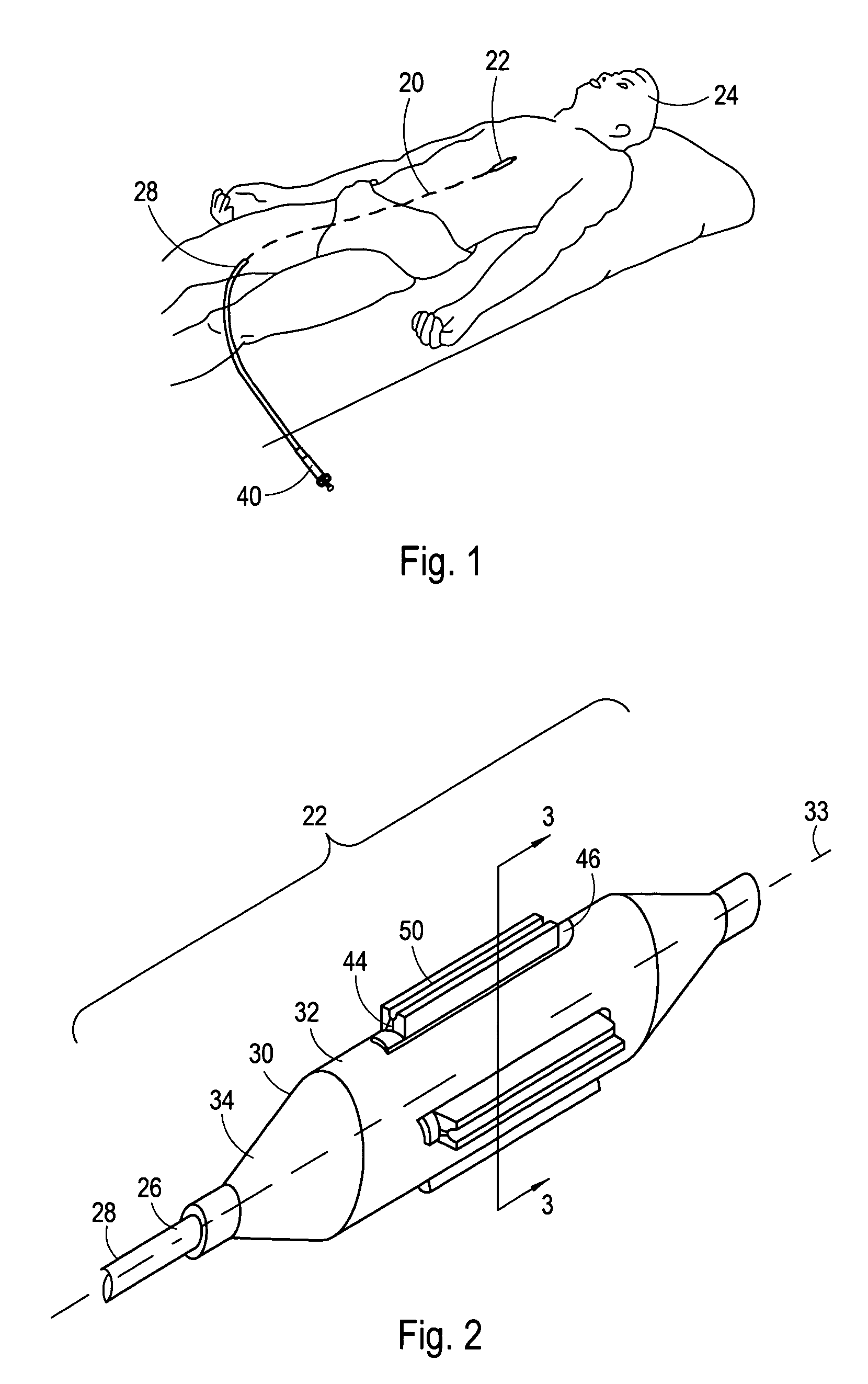
[0021]Referring initially to FIG. 1, a catheter 20 having a cutting balloon 22 is shown for performing a medical procedure at an internal treatment site of a patient 24. More specifically, the catheter 20 is shown positioned to treat a lesion in an upper body artery. Although the catheter 20 is capable of performing a medical procedure in an upper body artery such as a coronary artery, those skilled in the pertinent art will quickly recognize that the use of the catheter 20 as herein described is not limited to use in a specific artery, but, instead can be used in vascular conduits and other ductal systems throughout the human body.

[0022]Referring now to FIG. 2, the distal portion of the catheter 20 is shown to include a cutting balloon 22 that is attached to the distal end 26 of an inflation tube 28. FIG. 2 further shows that the cutting balloon 22 can include an inflatable balloon 30 that typically includes a cylindrical shaped working section 32 that defines an axis 33. Typically...


PUM


Abstract

A cutting balloon for use in a PTCA atherectomy procedure includes an elongated balloon that defines a longitudinal axis and is inflatable from a first deflated configuration to a second radially expanded configuration. One or more incising elements are mounted on the inflatable balloon. Compressible sheaths made of a relatively low durometer, flexible material are mounted on the balloon to protect the operative cutting surface of a respective incising element during assembly of the cutting balloon and transit of the cutting balloon to the treatment site. Each sheath extends farther from the longitudinal axis than the corresponding incising element and makes first contact with the tissue during a balloon inflation. Once contact has been established between the tissue and the sheath, further balloon inflation causes the sheath to radially compress between the tissue and the inflatable balloon exposing the operative cutting surface for tissue incision.

Description

FIELD OF THE INVENTION[0001]The present invention pertains generally to medical devices. More particularly, the present invention pertains to cutting balloon catheters for revascularization of coronary and peripheral vessels. The present invention is particularly, but not exclusively, useful as a cutting balloon having incising elements that are shielded when the balloon is deflated.BACKGROUND OF THE INVENTION[0002]Although conventional percutaneous transluminal coronary angioplasty (PTCA) procedures have been somewhat effective in treating coronary artery disease, cutting balloons are currently viewed by many as the next generation treatment option for the revascularization of both coronary and peripheral vessels. The cutting balloon mechanism is unique in that the balloon pressure is distributed over one or more incising elements (e.g. microtomes). The incising elements function as stress concentrators and cut initiators in PTCA atherectomy procedures. Consequently, PTCA atherecto...

Claims


Application Information

Patent Timeline
Patent Type & Authority Patents(United States)
IPC IPC(8): A61B17/22A61M29/00A61B17/32A61B17/00A61M25/10
CPCA61B17/320725A61B17/320758A61B17/22A61B17/32002A61B2017/00539A61B2017/00778A61B2017/22061A61B17/320016
Inventor O'BRIEN, DENNISYEE, CARL
Owner BOSTON SCI SCIMED INC
Learn More