
Emergency lighting system

a technology for emergency lighting and lighting systems, applied in the direction of testing/monitoring control systems, process and machine control, instruments, etc., can solve the problems of not helping occupants within the building or structure, unable to locate the exit location, and affecting the operation of emergency lights

Inactive Publication Date: 2010-09-21
LIVING SPACE INT
View PDF41 Cites 106 Cited by
  • Summary
  • Abstract
  • Description
  • Claims
  • Application Information

AI Technical Summary

Benefits of technology

[0005]The present invention provides an emergency lighting system that is able to guide and / or direct egress by occupants of an interior location of a structure, such as a building, ship or the like, based upon information relating to the location or locations of emergency situations within the interior location, such as a fire, whereby the occupants are guided away from obstructed or more hazardous locations and toward an appropriate egress.
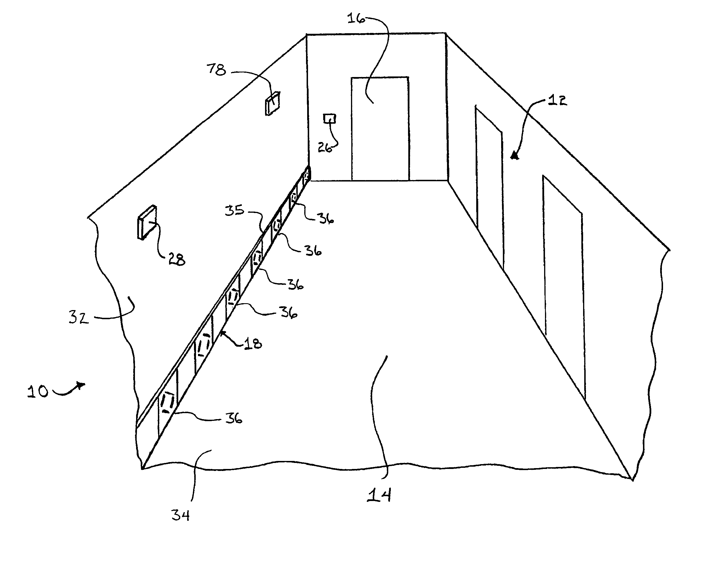
[0010]Therefore the present invention provides an emergency lighting system that is readily installable within all manner of interior locations of structures such as buildings and ships to selectively provide light signals that may guide occupants within the interior location both away from obstructed areas, based on the detected locations of emergency situations or hazardous areas, and out of the interior location. The guide light devices of the emergency lighting system are mountable to a generally vertical surface, and may form a base molding, or portion of a base molding, such that they are readily installable to new or existing structures and do not detract from the aesthetic appearance of the structure. In addition, the guide light devices are able to provide light signals that are less likely to be blocked by smoke and which may selectively direct occupants in either one of at least two directions via arrows and / or sequentially flashing lights that form a “chasing” pattern.

Problems solved by technology

However, such emergency lights may suffer from the disadvantage of being blocked by rising smoke during a fire.
In addition, some emergency lights merely provide illumination of an exit location or general illumination of an area, which may not help occupants within the building or structure that are not in view of the exit location, or are unfamiliar with the location of the exits.
While such emergency lights are able to provide light that is less likely to be obscured by smoke, these systems are typically costly, difficult to install, and cannot be readily utilized or retrofitted into existing buildings.

Method used


Image

  • Emergency lighting system
  • Emergency lighting system
  • Emergency lighting system

Examples


Embodiment Construction

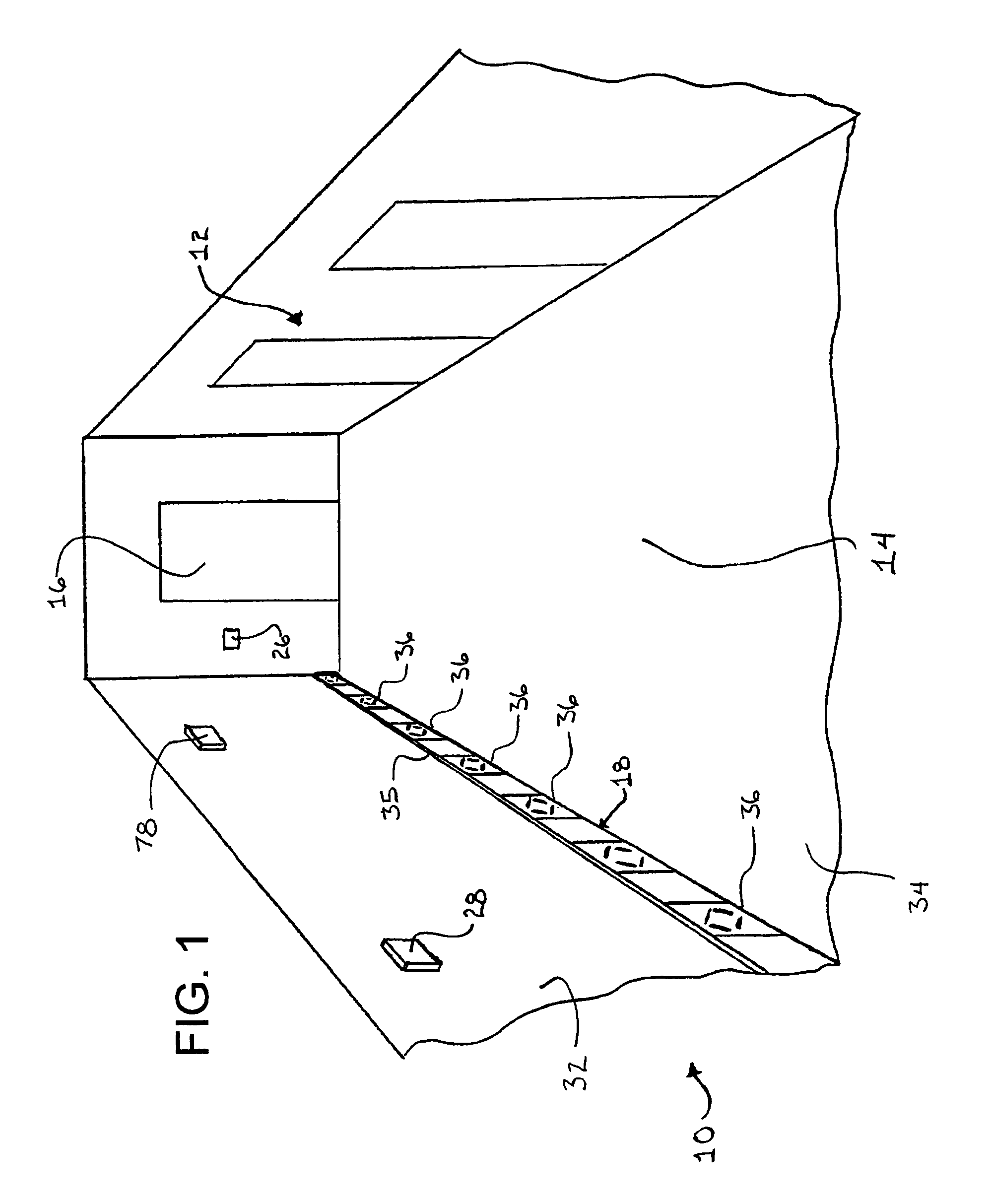
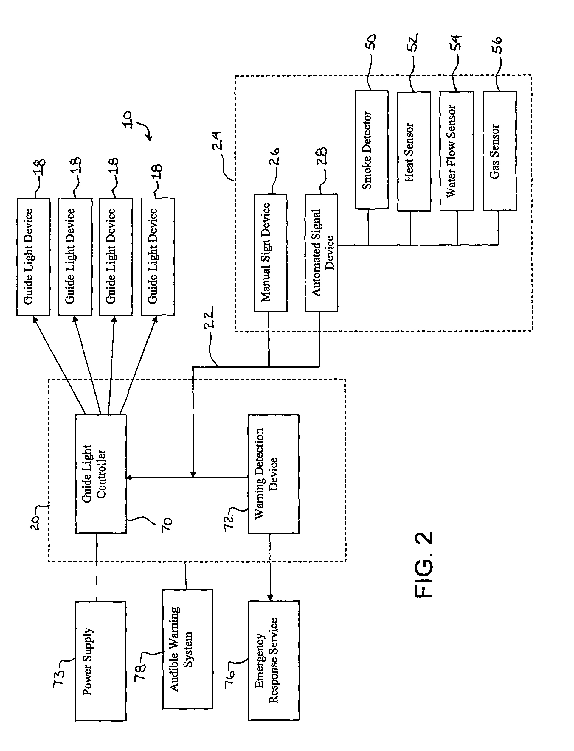
[0026]The present invention will now be described with reference to the accompanying figures, wherein the numbered elements in the following written description correspond to like-numbered elements in the figures. An emergency lighting system 10 is illustrated in FIG. 1 installed within an interior location 12, such as the hallway 14 shown, within a structure such as a building, shipping vessel, home or apartment building. Emergency lighting system 10 functions to guide and / or direct the egress of occupants from the interior location 12, such as toward an exit 16, in the event of an emergency situation occurring within interior location 12, such as a fire, explosion, or the like. Emergency lighting system 10 guides and directs occupants based upon the location of an emergency situation or hazardous location such that the occupants are able to avoid obstructed or more dangerous areas while egressing interior location 12, as discussed below.

[0027]Referring now also to FIGS. 1 and 2, e...


PUM


Abstract

An emergency lighting system comprises a control system, guide light devices, having multiple light members, guide light controllers, and signal devices. Each guide light controller is adapted to activate at least one guide light device operatively connected to the guide light controller to emit sequentially flashing light signals. Each signal device is adapted to selectively detect an emergency situation and transmit an emergency signal to the control system in response thereto, with each guide light controller being associated by the control system with one of the signal devices. The control system is adapted to transmit control signals in response to the emergency signals to selected ones of the guide light controllers, whereby the guide light controllers receiving emergency signals activate the guide light devices to emit sequentially flashing light signals in one of either two directions with the direction of flashing being controlled by the control signals.

Description

CROSS REFERENCE TO RELATED APPLICATION[0001]The present application claims priority of U.S. provisional application Ser. No. 60 / 779,736, filed Mar. 7, 2006, by James R. Hutchison for EMERGENCY LIGHTING SYSTEM, which is hereby incorporated herein by reference in its entirety.BACKGROUND OF THE INVENTION[0002]The present invention is directed to an emergency lighting system, and in particular to an emergency lighting system adapted to selectively provide light signals to guide occupants from an interior location.[0003]Emergency lights within interior locations are known that are caused to activate in the event of an emergency. Various forms of such emergency lights are mounted to ceilings or to walls in close proximity to ceilings. However, such emergency lights may suffer from the disadvantage of being blocked by rising smoke during a fire. In addition, some emergency lights merely provide illumination of an exit location or general illumination of an area, which may not help occupant...

Claims


Application Information

Patent Timeline
IPC IPC(8): G08B3/00
CPCG08B7/066
Inventor HUTCHISON, JAMES R.YAMAZAKI, MASATO
Owner LIVING SPACE INT
Learn More