
Diversity receiver, and method for receiving orthogonal frequency division multiplex signal

a receiver and orthogonal frequency technology, applied in the field of diversity receivers, can solve the problems of large reception signal equalizing errors, inability to stably receive the signal subjected to orthogonal frequency division multiplex, and poor reception state after switching, so as to prevent the level of reception from being lowered and stably receive the signal

Inactive Publication Date: 2010-09-21
JVC KENWOOD CORP A CORP OF JAPAN
View PDF11 Cites 5 Cited by
  • Summary
  • Abstract
  • Description
  • Claims
  • Application Information

AI Technical Summary

Benefits of technology

The present invention provides a diversity receiver for receiving signals through multiple antennas using orthogonal frequency division multiplex. The receiver includes amplification means for individually amplifying signals received through each antenna, attenuation means for individually attenuating the amplified signals, signal synthesis means for combining the attenuated signals, and control means for adjusting the attenuation amounts of the attenuation means. The control means adjusts the attenuation amounts to ensure stable reception of signals through the antennas and reduces errors in the signal equalization process. The receiver also includes a fix pointer for designating one of the attenuation means and a variable pointer for designating another attenuation means, allowing for proper attenuation amount control. The technical effect of the invention is to provide a reliable and efficient diversity receiver for stable reception of signals through multiple antennas.

Problems solved by technology

The reception state after switching may become worse than that before switching.
In this case, it becomes impossible to stably receive the signal subjected to orthogonal frequency division multiplex.
In this case, reception signal equalizing errors become large with a high possibility of demodulation errors.

Method used


Image

  • Diversity receiver, and method for receiving orthogonal frequency division multiplex signal
  • Diversity receiver, and method for receiving orthogonal frequency division multiplex signal
  • Diversity receiver, and method for receiving orthogonal frequency division multiplex signal

Examples


Embodiment Construction

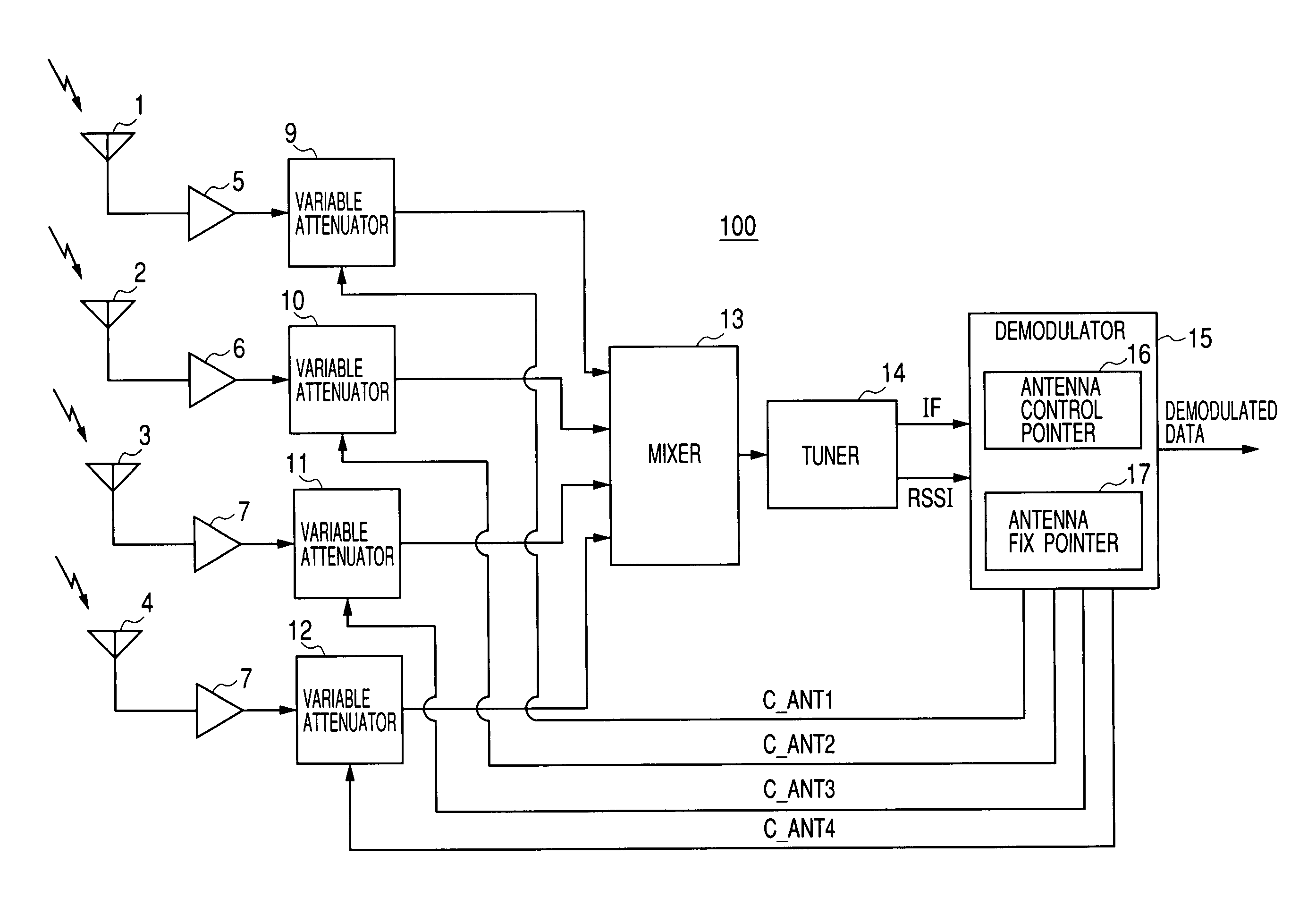
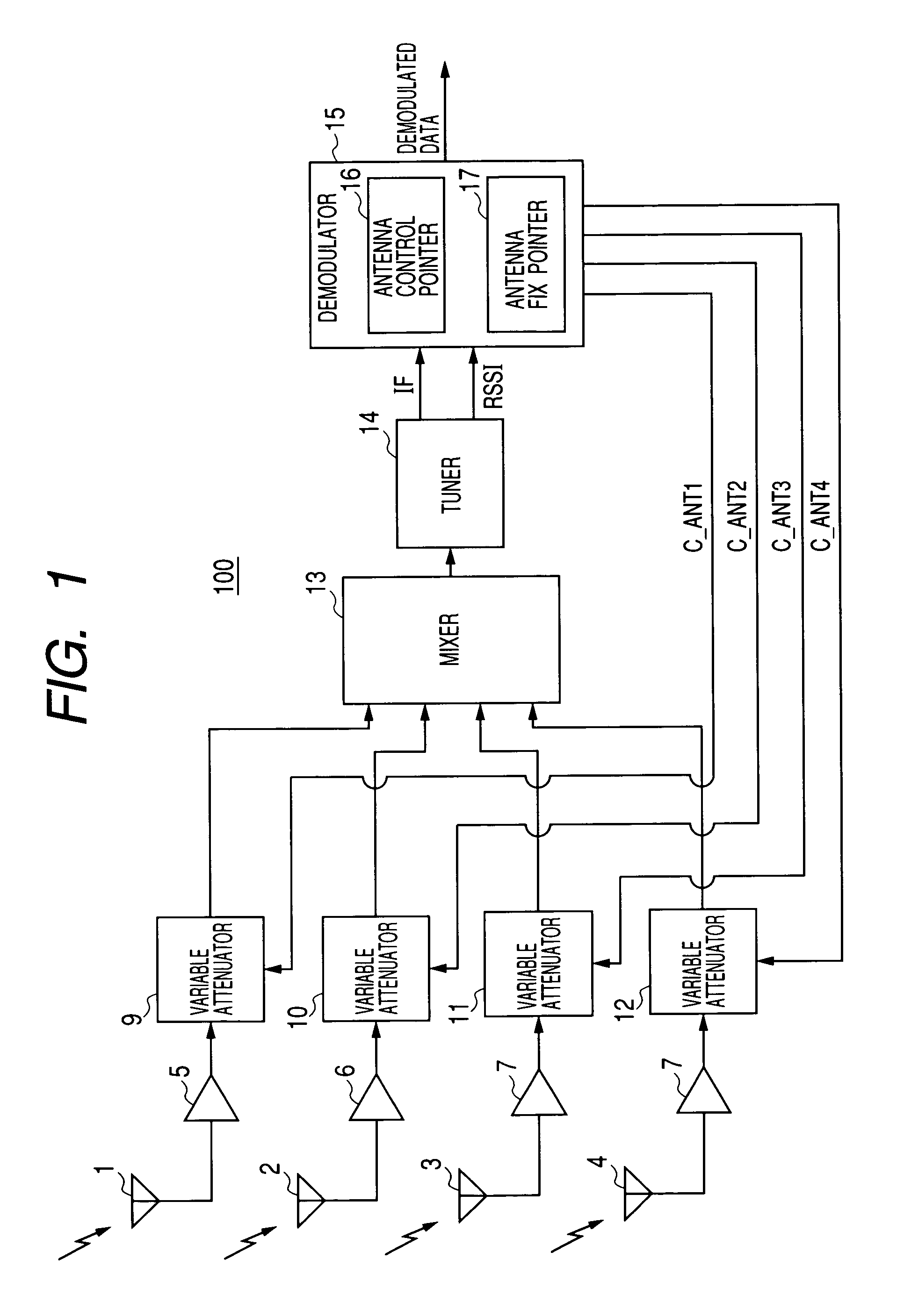
[0031]By referring to the accompanying drawings, detailed description will be given on a diversity receiver 100 according to an embodiment of the invention.

[0032]FIG. 1 is a diagram showing the structure of the diversity receiver 100 of the invention.

[0033]As shown, the diversity receiver 100 is constituted of a plurality of antennas 1 to 4, a plurality of low noise amplifiers (LNAs) 5 to 8, a plurality of variable attenuators 9 to 12, a mixer 13, a tuner 14 and a demodulator 15.

[0034]The plurality of antennas 1 to 4 receive radio frequency (RF) signals subjected to orthogonal frequency division multiplex (OFDM) on a transmission side and transmitted as a radio wave. The antenna 1 is coupled to the variable attenuator 9 via LNA 5. The antenna 2 is coupled to the variable attenuator 10 via LNA 6. The antenna 3 is coupled to the variable attenuator 11 via LNA 7. The antenna 4 is coupled to the variable attenuator 12 via LNA 8.

[0035]The RF signal subjected to orthogonal frequency divis...


PUM


Abstract

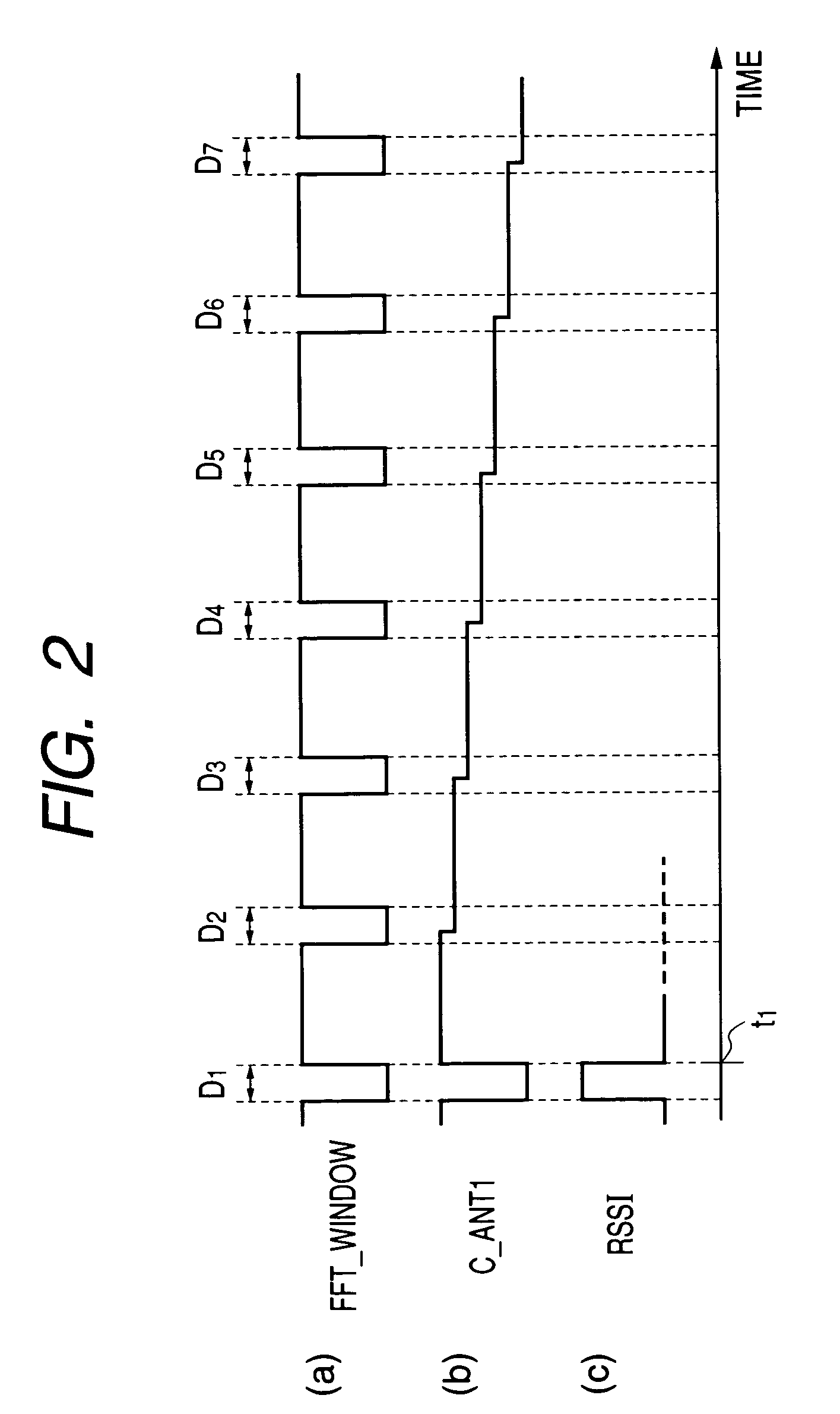
A diversity receiver capable of stably receiving an orthogonal frequency division multiplex signal, wherein a demodulator is so operated that the attenuation of the received signal is varied step by step every time a period corresponding to a guard interval section comes if it is determined that the reception level is increased by switching the attenuation in any one of variable attenuators, and the demodulator is so operated that the variable attenuator designated by an antenna control pointer is changed and the attenuation is varied if it is determined that the variable attenuator designated by an antenna control pointer is identical with the variable attenuator designated by an antenna fixing pointer.

Description

TECHNICAL FIELD[0001]The present invention relates to a diversity receiver for receiving a radio wave signal with a plurality of antennas, and more particularly to a diversity receiver for receiving a radio wave signal subjected to orthogonal frequency division multiplex on a transmission side.RELATED ART[0002]An orthogonal frequency division multiplex (OFDM) system is known as a system for transmitting radio wave digital signals.[0003]With this orthogonal frequency division multiplex system, digital signals are multiplexed by using a number of sub-carriers having different frequencies to efficiently transmit digital signals. With this orthogonal frequency division multiplex system, a guard interval section is set before an effective symbol section so that the reception characteristics can be prevented from being degraded by inter-symbol interference even if a multi-path is formed.[0004]A diversity receiver of an antenna switching type such as shown in FIG. 9 is known which alleviat...

Claims


Application Information

Patent Timeline
Patent Type & Authority Patents(United States)
IPC IPC(8): H04J11/00G01R31/08H04J1/00H04W4/00H03C7/02H04B7/08H04L1/06H04L27/26
CPCH04B7/08H04B7/0848H04L1/06H04L27/2647H04B7/0805
Inventor OKUHATA, YASUHIDESHINODA, ATSUSHI
Owner JVC KENWOOD CORP A CORP OF JAPAN
Learn More