Fire-fighting monitor

a monitor and monitor technology, applied in fire rescue, pipe joints, adjustable joints, etc., can solve the problems of reducing fluid flow energy, reducing flow efficiency, and limited directional control, and achieves small storage space and simple and inexpensive design.

Active Publication Date: 2010-09-28
ELKHART BRASS MFG
View PDF36 Cites 11 Cited by
  • Summary
  • Abstract
  • Description
  • Claims
  • Application Information

AI Technical Summary

Benefits of technology

[0004]Accordingly, the present invention provides a fire-fighting monitor that is adapted to flex along a substantial portion of its length to control the direction of fluid flow through the monitor, to provide an efficient fluid path through the monitor, to require a relatively small stowage space, and to do so with a relatively simple and inexpensive design.
[0015]Accordingly, the monitor of the present invention provides a monitor with improved flexibility, higher flow-efficiency, smaller stowage size, and relatively low complexity.

Problems solved by technology

Typical monitors are made up of curved and straight pipes or conduits, some of which may be rotatably or rigidly mounted to one another, and commonly include curves in different directions, which reduces flow efficiency.
Therefore, typical monitors provide limited directional control over the fluid that they convey, by rotating about a single vertical pivot axis and pivoting about one or two horizontal axes for elevational change, and can significantly reduce the fluid flow energy by causing abrupt or multiple changes in flow direction.
Typical monitors may also include a relatively large number of different parts, adding cost and complexity.
Further, because monitors typically have little flexibility, they occupy a relatively large amount of horizontal and vertical space when not in use, and can exhibit a large swing radius when rotated.
Thus, typical monitors may prevent vehicles to which they are attached from being stored in certain garages or from passing through low-clearance areas, and may reduce the space available for other equipment in the vicinity of the monitor, for example.

Method used


Image

  • Fire-fighting monitor
  • Fire-fighting monitor
  • Fire-fighting monitor

Examples


Embodiment Construction

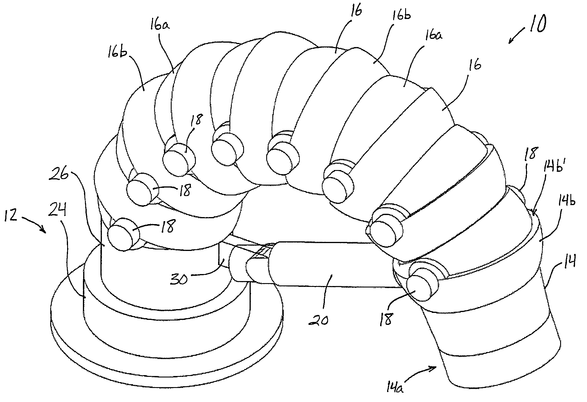
[0025]Referring to FIG. 1, the numeral 10 generally designates a fire-fighting monitor of the present invention. As will be more fully described below, monitor 10 is adapted to exhibit increased flexibility, an efficient fluid path, and a compact stowage configuration.

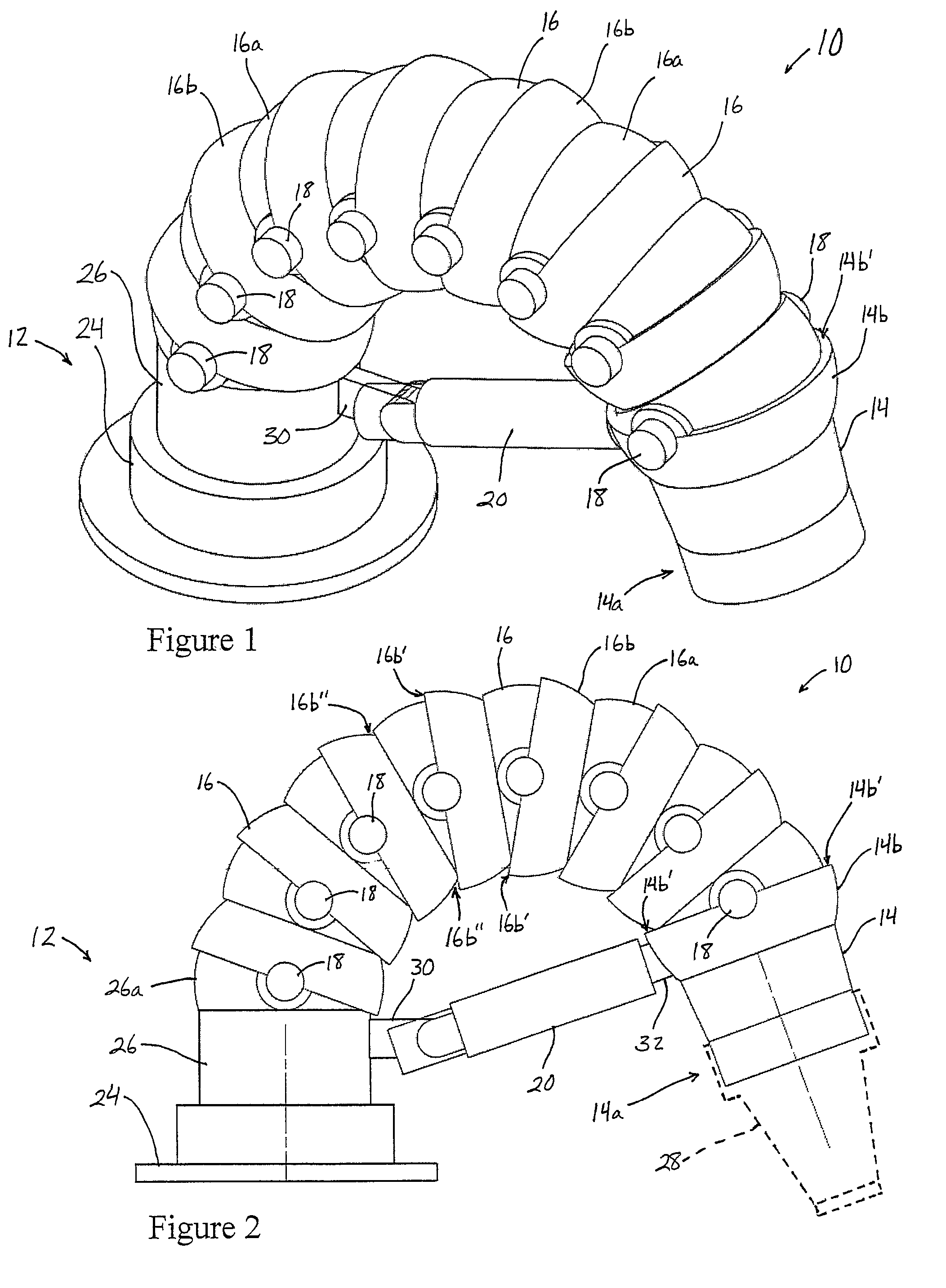
[0026]Referring to FIGS. 1-4, monitor 10 includes a base 12 defining an inlet, an outlet 14, and a plurality of hollow members 16 arranged in series between base 12 and outlet 14. Each hollow member 16 is coupled or connected to an adjacent hollow member 16 via a pair of joints 18, each pair of joints providing a pivot axis. Additionally, one hollow member is coupled or connected to base 12 and another hollow member is coupled or connected to a hollow member configured as an outlet 14 to thereby form a flexible monitor body that extends from the base to the outlet.

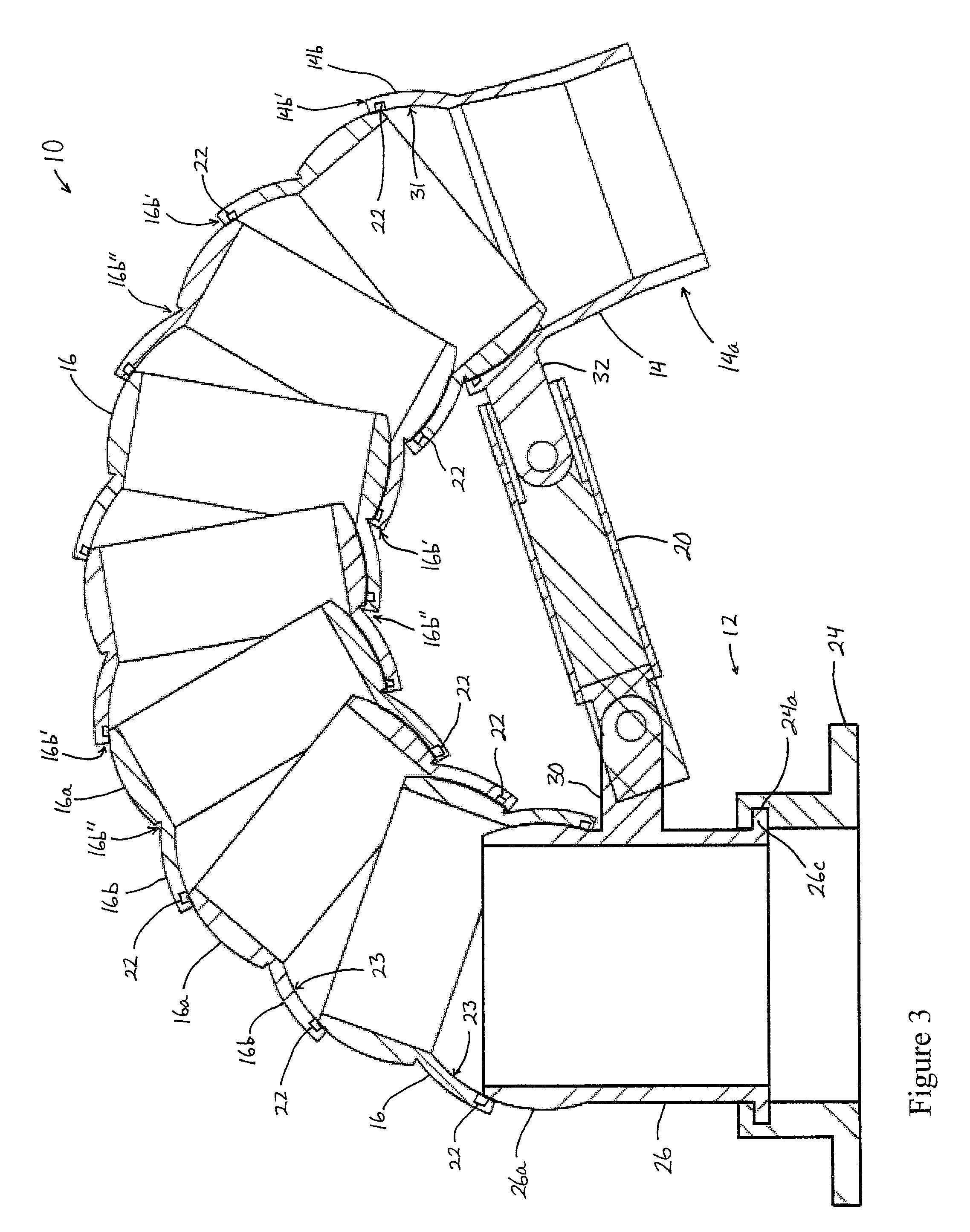
[0027]Thus, the hollow members are pivotally mounted to one another in series about a plurality of pivot axes to form a straight fluid path (FIGS. 4 and 5) o...


PUM


Abstract

A fire-fighting monitor includes a base, an outlet, and a plurality of jointed hollow members forming a flexible body. The hollow members are pivotably coupled together and extend between the base and the outlet to provide a flexible fluid path. A base-end hollow member is coupled to the base, and an outlet-end hollow member is coupled to the outlet. Each of the hollow members has a ball portion and a socket portion, with the socket portions adapted to receive the ball portions and form a seal therebetween. Optionally, a drive unit may be incorporated into the base for rotatably driving the fire-fighting monitor.

Description

CROSS REFERENCE TO RELATED APPLICATION[0001]The present invention claims the benefit of U.S. provisional application Ser. No. 60 / 947,188, filed Jun. 29, 2007, which is hereby incorporated herein by reference in its entirety.FIELD OF THE INVENTION[0002]The present invention is directed to a fire-fighting monitor and, more specifically, to a fire-fighting monitor that is flexible and configurable into a compact stowage configuration.BACKGROUND OF THE INVENTION[0003]Fire-fighting monitors are used to direct the flow of water or other fire-fighting fluid and include an inlet, which is connected to a hose or pipe, and a discharge outlet to which a nozzle or stream-shaper is mounted. Monitors are typically mounted to fire-fighting vehicles and / or aerial ladders and deliver a large quantity of fluid (typically water or foam) either directly to a fire, or to a fire via a hose or other conduit. Typical monitors are made up of curved and straight pipes or conduits, some of which may be rotata...

Claims


Application Information

Patent Timeline
Patent Type & Authority Patents(United States)
IPC IPC(8): A62C25/00F16L27/04B05B15/06B05B15/08F16L27/06A62C27/00B05B15/68
CPCA62C31/02B05B15/066B05B15/652
Inventor COMBS, ERIC NATHANIELLOZIER, TODD BRIAN
Owner ELKHART BRASS MFG
Why Eureka
Try Eureka