Locking structure

a technology of locking structure and locking body, which is applied in the field of locking structure, can solve the problems of considerable reduction of storage space defined by the center cap and the console device body, and significantly limited design freedom, so as to reduce the storage space of the console device, improve the locking structure, and minimize space

Inactive Publication Date: 2010-09-28
HONDA MOTOR CO LTD
View PDF9 Cites 50 Cited by
  • Summary
  • Abstract
  • Description
  • Claims
  • Application Information

AI Technical Summary

Benefits of technology

[0004]In view of the foregoing prior art problems, it is an object of the present invention to provide an improved locking structure which can lockingly attach a desired object to a wall portion of a console device with a minimized space between the desired object and the wall portion and hence without reducing a storage space of the console device.
[0005]In order to accomplish the above-mentioned object, the present invention provides an improved locking structure for lockingly attaching a desired object to a wall portion of a console device, which comprises a locking claw portion formed on the desired object, and a locking clamp mechanism formed on the wall portion. The locking clamp mechanism having a fitting hole portion formed in the wall portion for fitting therein of the locking claw portion of the desired object, a locking support portion for lockingly supporting the locking claw portion fitted in the fitting hole portion, a pair of opposed movement-preventing projecting portions formed on opposite ends of the locking support portion for preventing movement or displacement of the desired object toward (i.e., between) the opposite ends, and an elastic portion extending from the wall portion for resiliently pressing the locking claw portion against the locking support portion.
[0007]Further, as the locking claw portion of the desired object is fitted into the fitting hole portion, the locking claw portions come to rest on the locking support portion continuous with the edge of the fitting hole portion, so that a load or weight of the desired object can be appropriately supported by the locking support portion. Thus, the desired object can be supported with an increased reliability.
[0008]Further, as the locking claw portion of the desired object is fitted into the fitting hole portion, the locking claw portion is brought into face-to-face abutment with the opposed movement-preventing projecting portions to be sandwiched between the movement-preventing projecting portions, the desired object can be effectively prevented from undesirably jolting between the movement-preventing projecting portions and thus can be reliably supported in a predetermined position without being displaced parallel to the wall portion between the movement-preventing projecting portions.
[0009]Preferably, the desired object has the locking claw portion on each of its opposite (e.g., left and right) side walls, and the locking clamp mechanism is formed on each of opposed (e.g., left and right) wall portions of the console device. Namely, two locking structures constructed according to the present invention are provided, so that the desired box can be lockingly attached at its opposite sides to the opposed wall portions and thus can be appropriately kept supported in the predetermined position with an even further enhanced reliability.

Problems solved by technology

In the former case, a storage space defined by the center cap and the console device body would be considerably reduced due to the provision of the additional locking support structures, while, in the latter case, design freedom would be considerably limited because some measure for increasing the mechanical strength of the center cap is required.

Method used


Image

  • Locking structure
  • Locking structure
  • Locking structure

Examples


Embodiment Construction

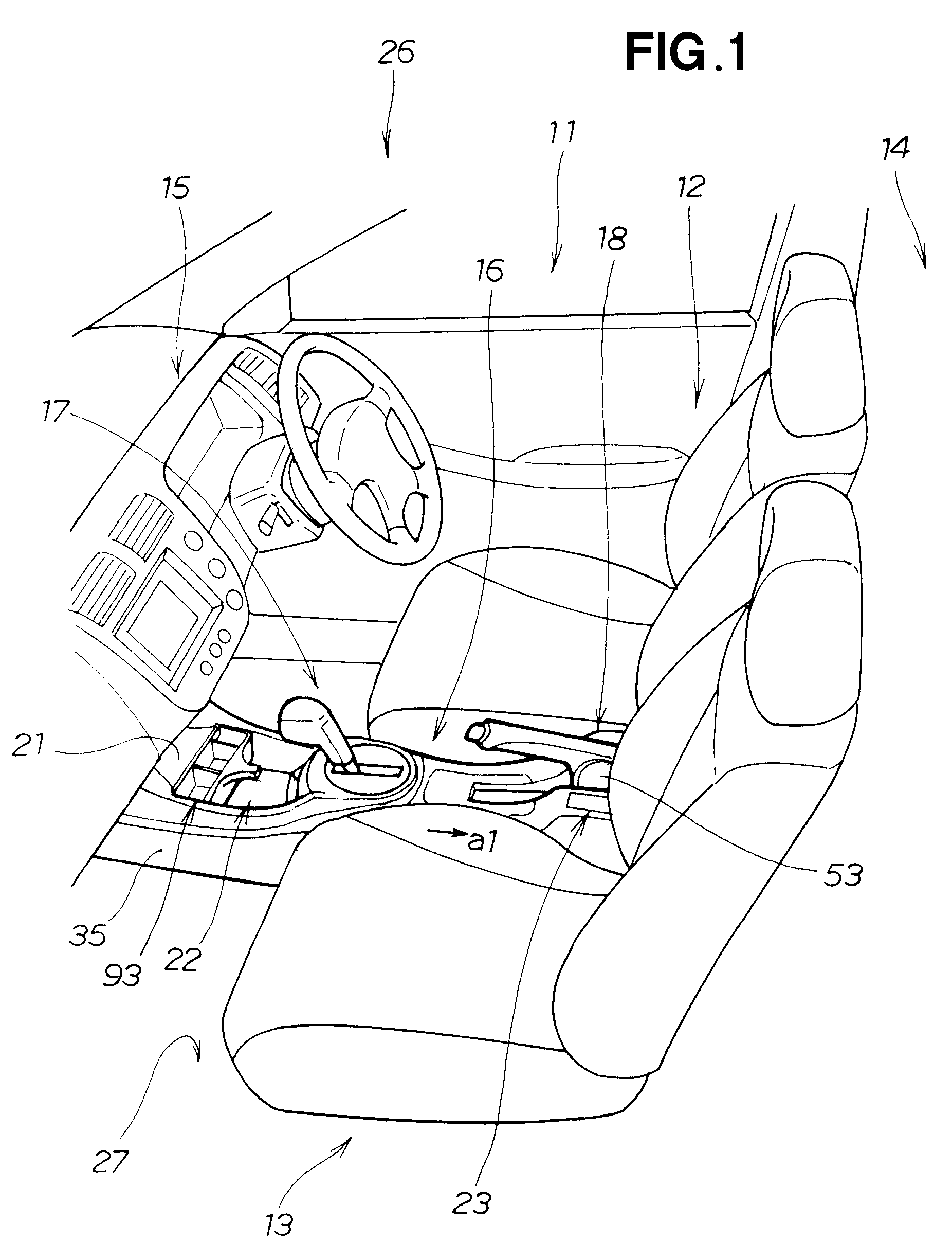
[0022]FIG. 1 is a perspective view showing a compartment 11 of a vehicle 26 and more particularly a center console 16 employing locking structures of the present invention.

[0023]In the vehicle compartment 11, there are provided a driver seat 12, a front passenger seat 13, rear seats 14, an instrument panel 15, the center console (box) 16, a shift lever mechanism 17 and a parking brake lever mechanism 18.

[0024]The center console 16 is disposed between the driver seat 12 and the front passenger seat 13, and it includes a front storage section 21 located proximate to the instrument panel 15, a front cup holder 22 located rearwardly (i.e., as indicated by arrow a1) of the front storage section 21 and a CD case section 23. For example, the vehicle 26 employs an automatic transmission (AT), and the shift lever mechanism 17 of the automatic transmission is disposed on a floor or underbody 27.

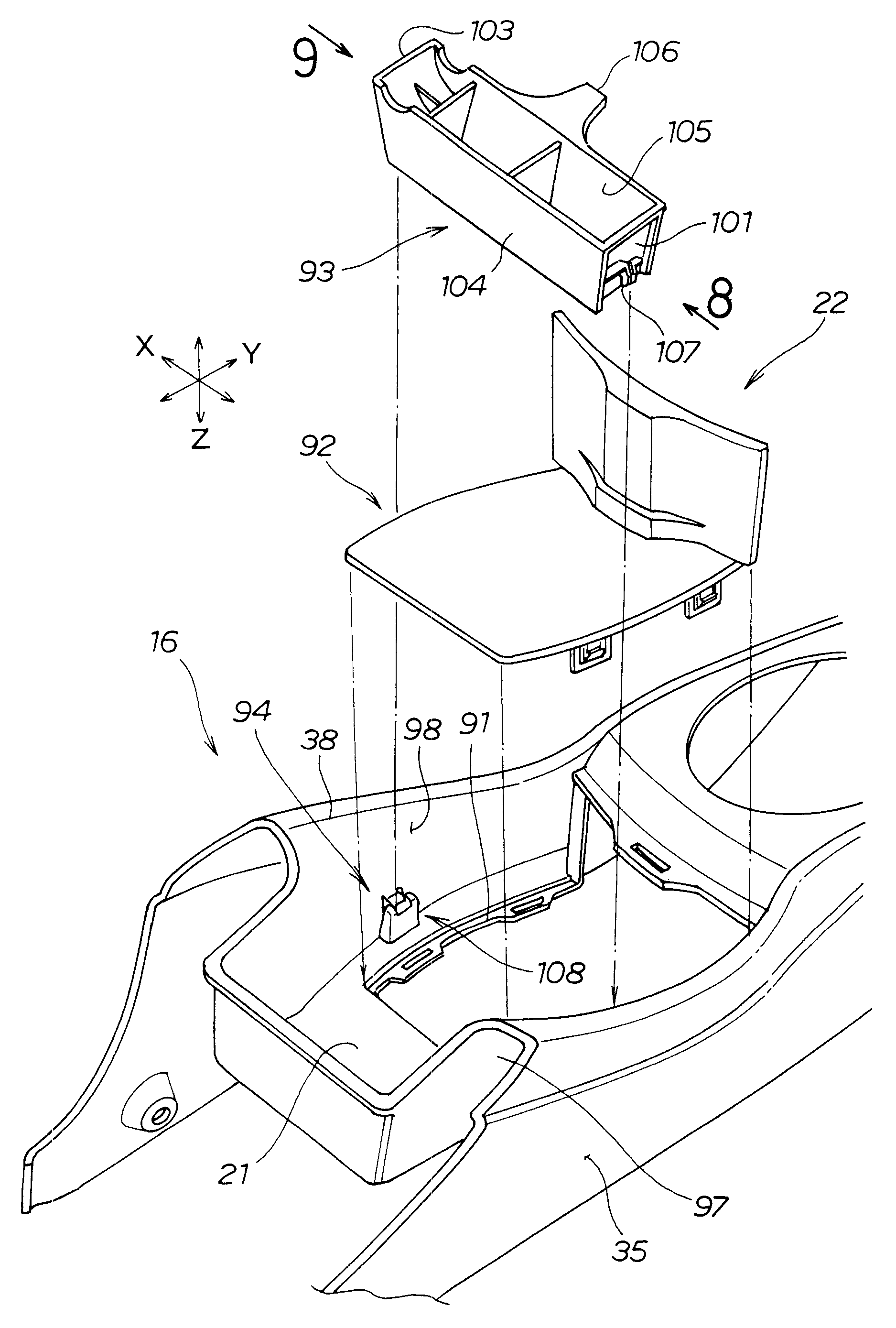
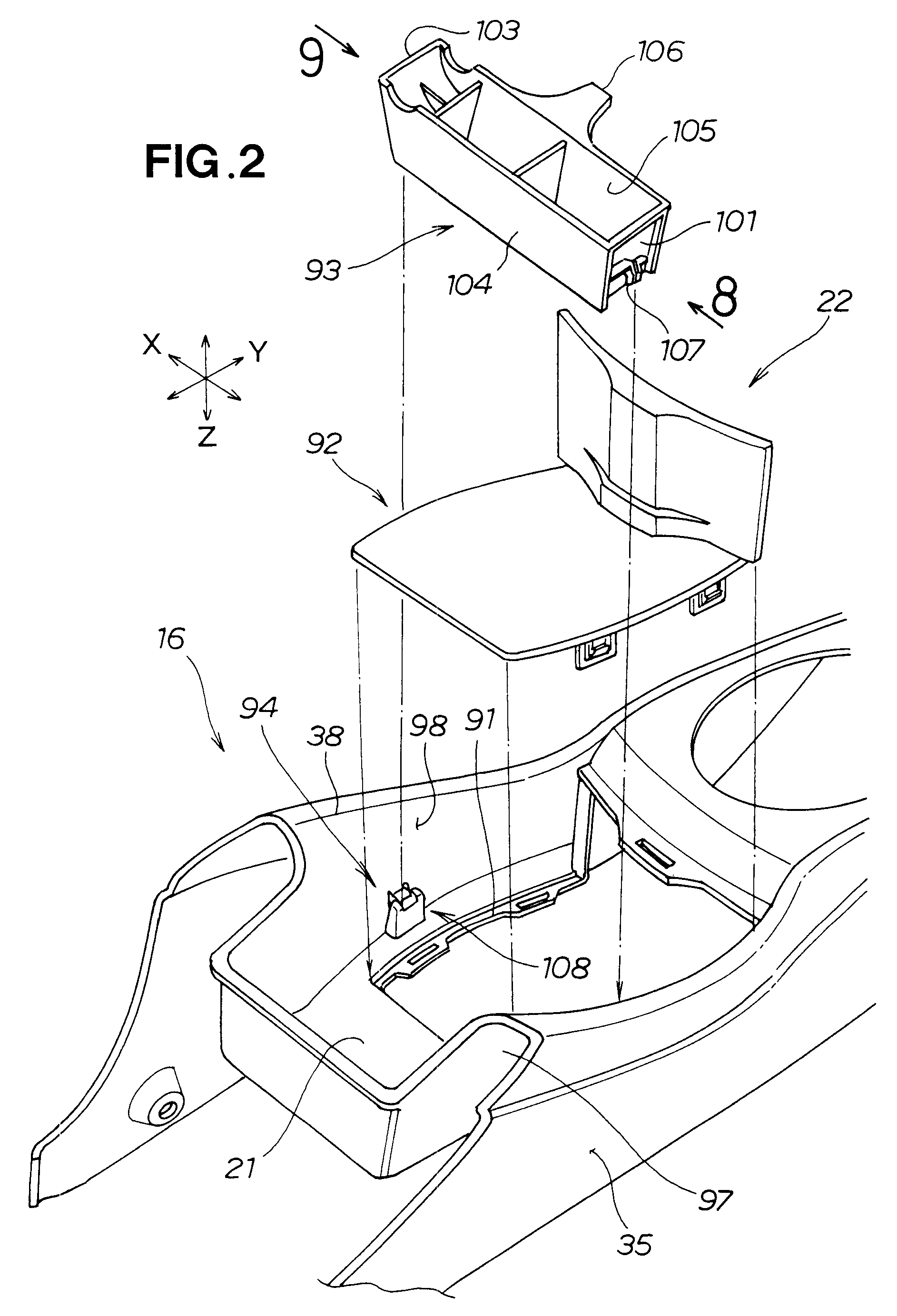
[0025]FIG. 2 is an exploded perspective view of the locking structures 94 of the present invention,...


PUM


Abstract

Locking structures each include a locking claw portion formed on a desired object, and a locking clamp mechanism formed on at least one of left and right wall portions of a console device. The clamp mechanism has a fitting hole portion formed in the wall portion for fitting therein of the locking claw portion, a locking support portion for lockingly supporting the claw portion fitted in the fitting hole portion, and a pair of opposed movement-preventing projecting portions formed on opposite ends of the support portion for preventing movement of the object between the opposite ends. The clamp mechanism also having a resiliently-deformable elastic portion formed integrally with the wall portion to extend into the hole portion for resiliently pressing the claw portion against the support portion.

Description

FIELD OF THE INVENTION[0001]The present invention relates to an improved locking structure for lockingly attaching a desired object to a wall portion of a console device.BACKGROUND OF THE INVENTION[0002]Generally, in vehicle compartments, there are employed locking structures for lockingly attaching desired objects to wall portions of various components of the vehicle. Such locking structures are disclosed, for example, in Japanese Patent Application Laid-Open Publication No. 2004-196083 (JP 2004-196083 A). According to the disclosure of JP 2004-196083, a plurality of locking structures are provided on a console device disposed between a driver set and a front passenger seat, and a center cap is mounted, via the locking structures, in a working opening section formed in the console device, to close the working opening section. As the center cap is placed on mounting seating surface portions, formed on peripheral edges of the working opening section, with claw portions of the center ...

Claims


Application Information

Patent Timeline
Patent Type & Authority Patents(United States)
IPC IPC(8): B60R7/04
CPCB60R13/0262Y10T70/5889
Inventor ISAYAMA, HIROYUKISEINO, HAJIME
Owner HONDA MOTOR CO LTD
Why Eureka
Try Eureka