Direct-type backlight device

a backlight device and direct-type technology, which is applied in the direction of diffusing elements, lighting and heating apparatus, instruments, etc., can solve the problems of insufficient luminance, reduced availability of linear light source light quantity, and uneven period luminance, so as to reduce the uneven luminance on the illuminating surface, increase the luminance observed, and reduce the electric power consumption

Inactive Publication Date: 2010-09-28
ZEON CORP
View PDF8 Cites 9 Cited by
  • Summary
  • Abstract
  • Description
  • Claims
  • Application Information

AI Technical Summary

Benefits of technology

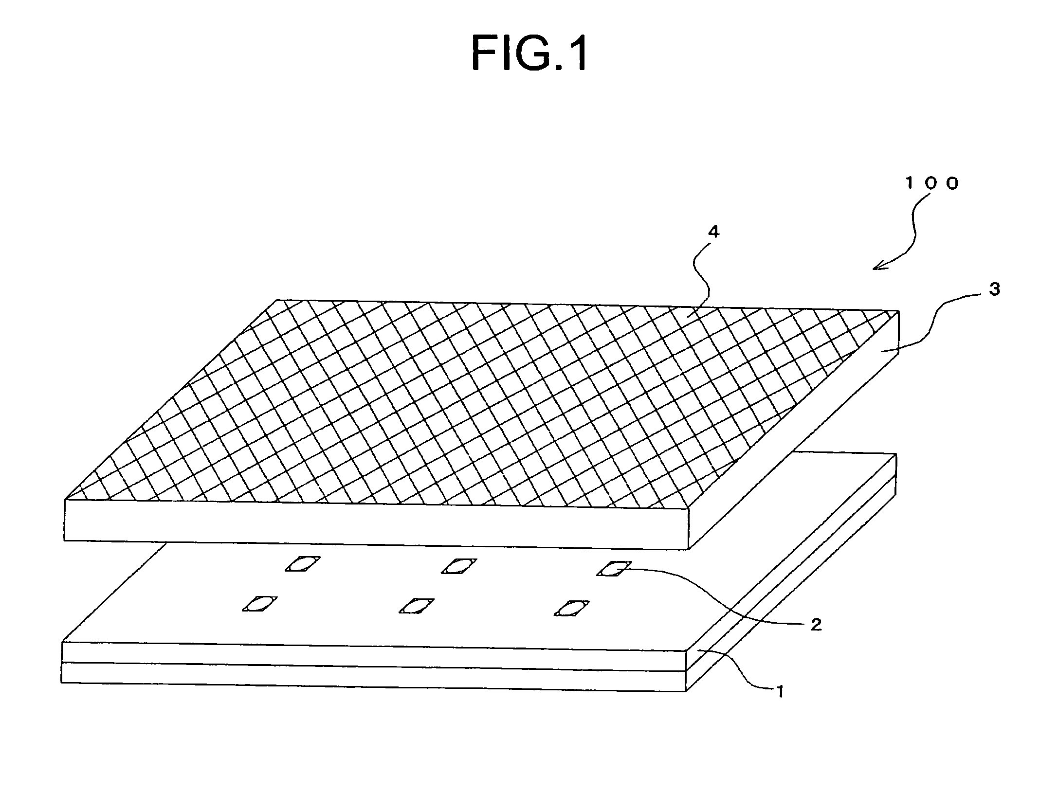
[0025]According to the direct-type backlight device of the present invention, by providing with a split image forming member which produces the image of the point light source which is observed within the specific region, it is possible to greatly reduce the luminance unevenness on the illuminating surface. Also by using the plurality of point light sources, it is possible to increase the luminance observed from the front direction with reducing the electric power consumption compared with the case of using the linear light source.

Problems solved by technology

On the illuminating surface of such a direct-type backlight device, there is a tendency that the position right above the linear light source has high luminance, and the luminance becomes lower as leaving from the right-above position, which sometimes causes the periodic luminance unevenness.
However, in this method, an availability of the light quantity irradiated from the linear light source is reduced and the sufficient luminance is not obtained because a part of the light quantity is blocked by the light quantity correcting pattern.
However, even if the point light source is used as the light source of the direct-type backlight device, there still was a problem of the luminance unevenness occurring on the illuminating surface as was in the prior art.

Method used


Image

  • Direct-type backlight device
  • Direct-type backlight device
  • Direct-type backlight device

Examples


example 10

Preparative Example 10

Pellet D for Light Diffusing Plate

[0113]Pellets D for the light diffusing plate were produced in the same manner as in Preparative Example 1, except that the amount of the resin was 99.6 parts and the amount of the light diffusing agent was 0.4 parts. Using these pellets D for the light diffusing plate as the raw material, a test plate was prepared, and total light transmittance and haze thereof were measured in the same manner as in Preparative Example 1. The total light transmittance of the test plate was 81% and the haze thereof was 99%.

example 11

Preparative Example 11

Pellet E for Light Diffusing Plate

[0114]The aforementioned resin as it was without addition of the light diffusing agent was used for preparing pellets E for the light diffusing plate. Using these pellets E for the light diffusing plate as a raw material, a test plate was prepared, and total light transmittance and haze thereof were measured in the same manner as in Preparative Example 1. The total light transmittance of the test plate was 92% and the haze thereof was 0.5%.

example 12

Preparative Example 12

Stamper 7

[0115]A nickel-phosphorus non-electrolytic plating of 100 μm thickness was formed on an entire surface of a stainless steel SUS430 (JIS G4305) having the size of 387 mm×308 mm×thickness of 100 mm. Using a monocrystal diamond cutting tool having the apex angle of 100 degrees, the nickel-phosphorus non-electrolytically plated surface was cut to form a plurality of triangle grooves having a pitch of 70 μm and an apex angle of 100 degrees. The grooves were formed along a direction parallel to the side of 308 mm length (short side direction). A stamper 7 having linear convexed structures having a triangle cross-sectional shape on the nickel-phosphorus non-electrolytically plated surface was thus produced.


PUM


Abstract

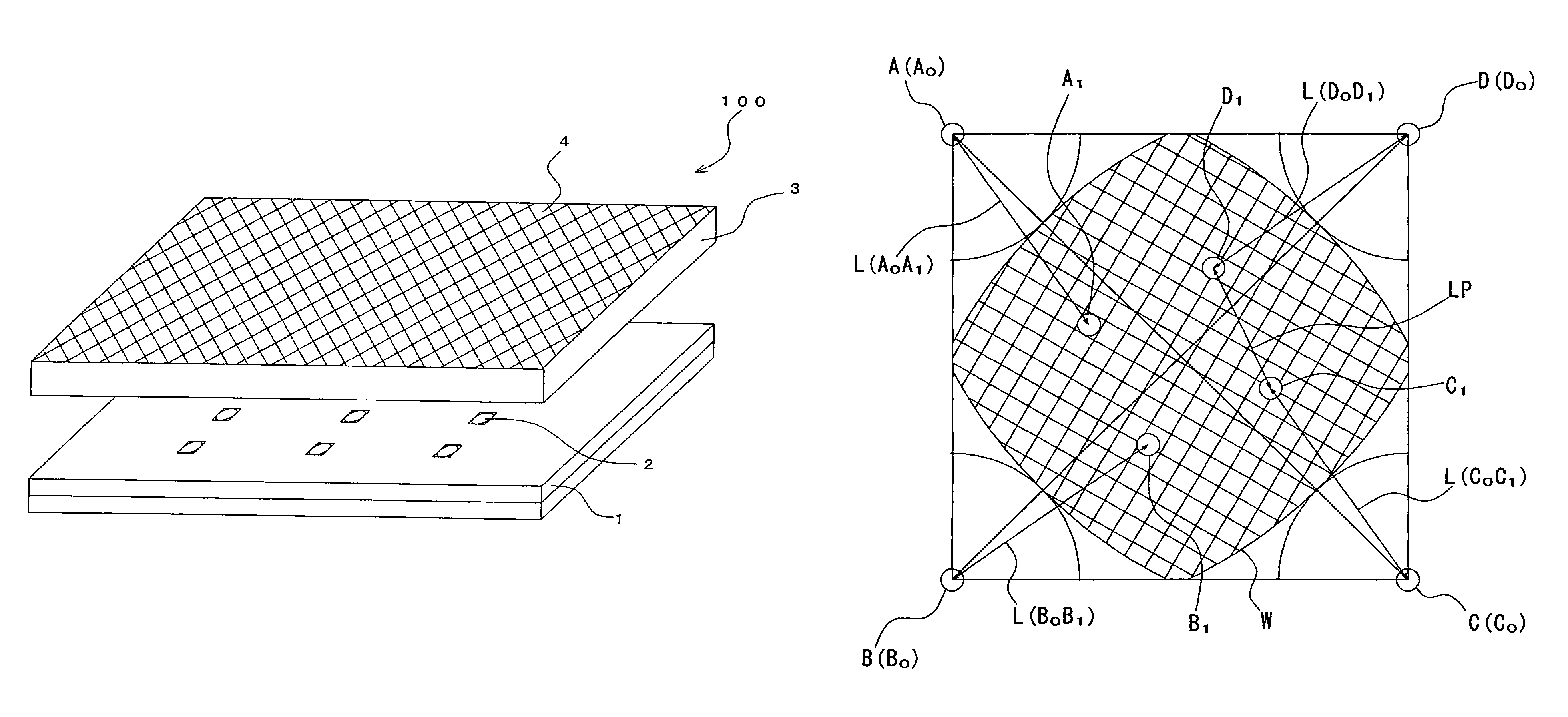
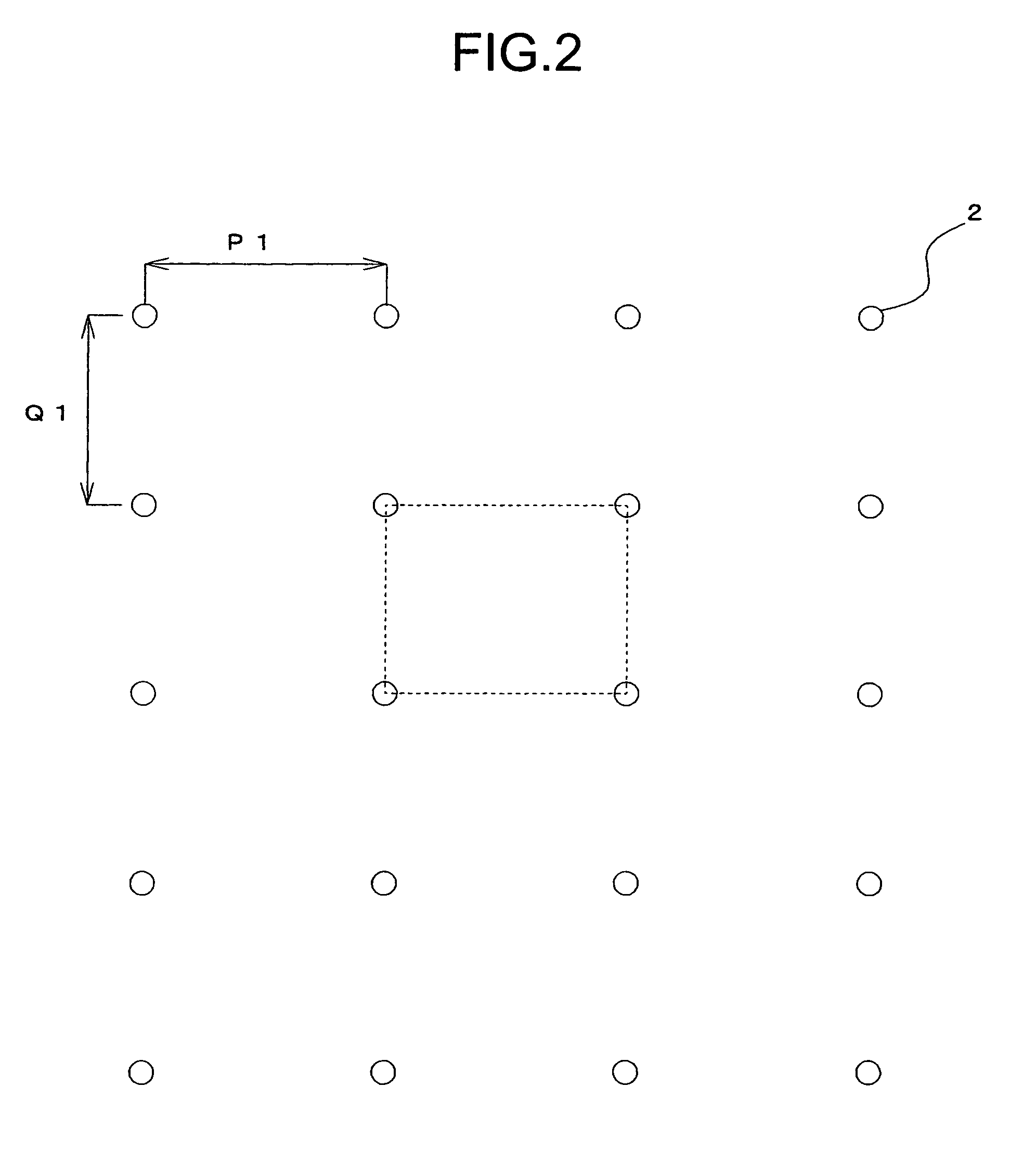
The direct-type backlight device of the present invention includes a reflecting plate, a plurality of point light sources and a light diffusing plate in this order. A light emitting surface of the light diffusing plate is provided with a fine concavo-convex structure which is a split image forming member. By the fine concavo-convex structure, images A1, B1, C1 and D1 on the light emitting surface corresponding to four point light sources A, B, C and D which constitute a convex quadrilateral which has the smallest area and the shortest circumference length among the plurality of point light sources are observed in a specific region W in a region surrounded by positions A0, B0, C0 and D0 which are positions of the projected image of the point light sources A, B, C and D on the light diffusing plate.

Description

TECHNICAL FIELD[0001]The present invention relates to a direct-type backlight device, and particularly relates to a direct-type backlight device which is provided with a plurality of point light sources and has a greatly reduced luminance unevenness on a illuminating surface.BACKGROUND ART[0002]Conventionally, as an example of a commonly used backlight device for liquid crystal displays, there is known a direct-type backlight device which is provided, in this order, with a reflecting plate, a plurality of linear light sources (e.g., cold cathode tubes) arranged in approximately parallel, and a light diffusing plate acting as a illuminating surface by diffusing and then emitting direct light from these linear light sources and reflected light on the reflecting plate. On the illuminating surface of such a direct-type backlight device, there is a tendency that the position right above the linear light source has high luminance, and the luminance becomes lower as leaving from the right-...

Claims


Application Information

Patent Timeline
Patent Type & Authority Patents(United States)
IPC IPC(8): F21V7/04F21V13/10
CPCG02B5/0231G02B5/0242G02B5/0278G02F1/133611G02F2001/133613G02F1/133603G02F1/133606G02F2001/133607G02F1/133613G02F1/133607G02B5/02G02F1/1335
Inventor SUZUKI, TOSHIAKITSUKADA, KEISUKE
Owner ZEON CORP
Why Eureka
Try Eureka