
Plug connector with improved cable arrangement and convenient assembly

a plug connector and cable arrangement technology, applied in the field of plug connectors, can solve the problems of inconvenient assembly, contact bending or wire bending, and the arrangement of signal and power wires above cannot meet the requirements, so as to achieve convenient assembly and use, and improve the cable arrangement

Inactive Publication Date: 2010-09-28
HON HAI PRECISION IND CO LTD
View PDF8 Cites 22 Cited by
  • Summary
  • Abstract
  • Description
  • Claims
  • Application Information

AI Technical Summary

Benefits of technology

The present invention provides a plug connector with improved cable arrangement for convenient assembly and use. The connector includes an insulative housing with a base portion and a mating portion, contacts, a circuit board with through holes, and wires (signal wires and power wires) that connect with the contacts. The signal wires are soldered on the circuit board and extend laterally along a perpendicular direction, while the power wires are soldered with the contacts or directly connected with the circuit board and extend along a perpendicular direction. The technical effects of this design include easy assembly and use, reliable electrical connection, and efficient signal transmission.

Problems solved by technology

In some cases, the arrangement of the signal and power wires stated above cannot meet the requirements.
In addition, such manner of bending the contacts or the wires is inconvenient in assembly.

Method used


Image

  • Plug connector with improved cable arrangement and convenient assembly
  • Plug connector with improved cable arrangement and convenient assembly
  • Plug connector with improved cable arrangement and convenient assembly

Examples


Embodiment Construction

[0022]Reference will now be made to the drawing figures to describe the present invention in detail.

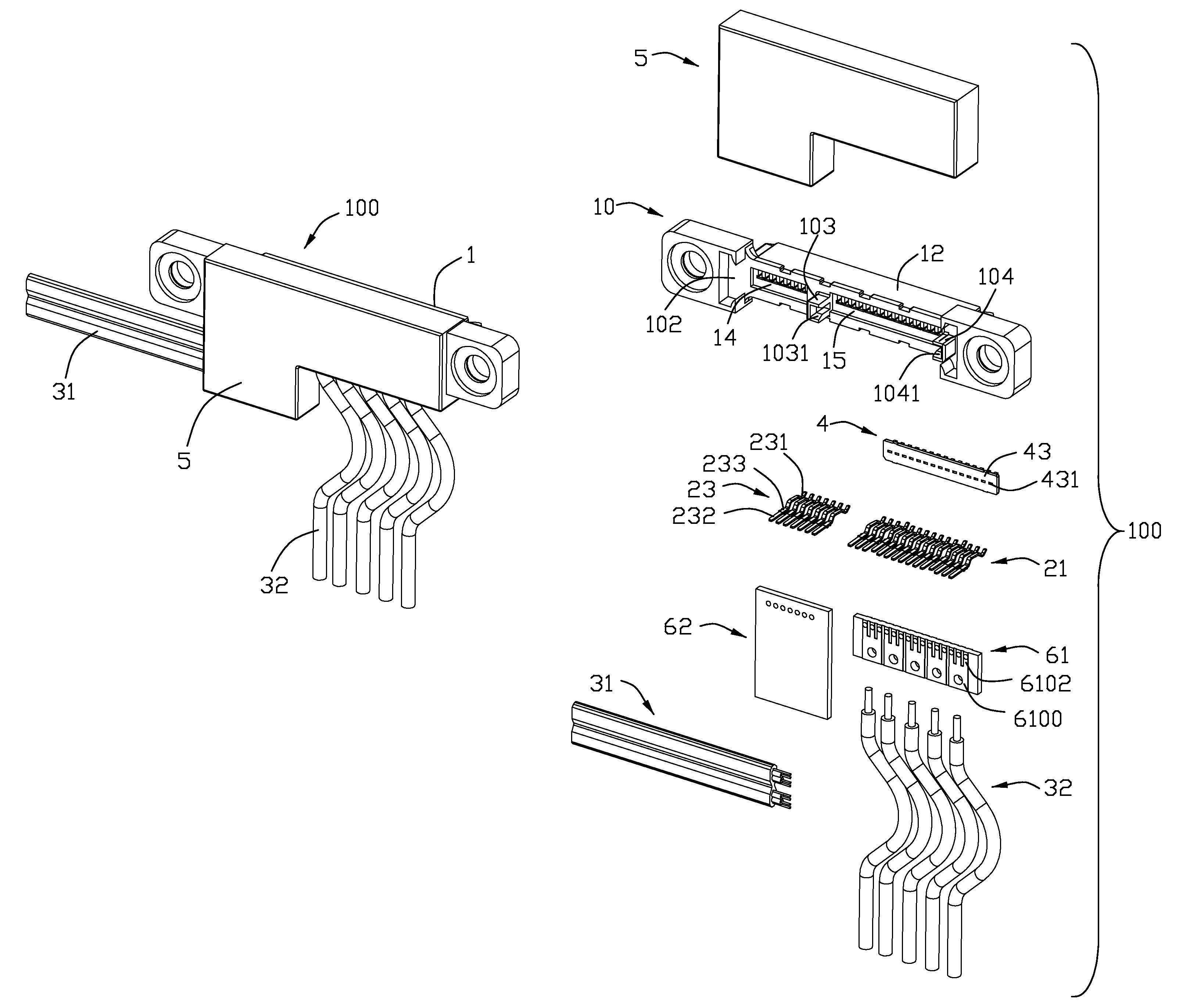
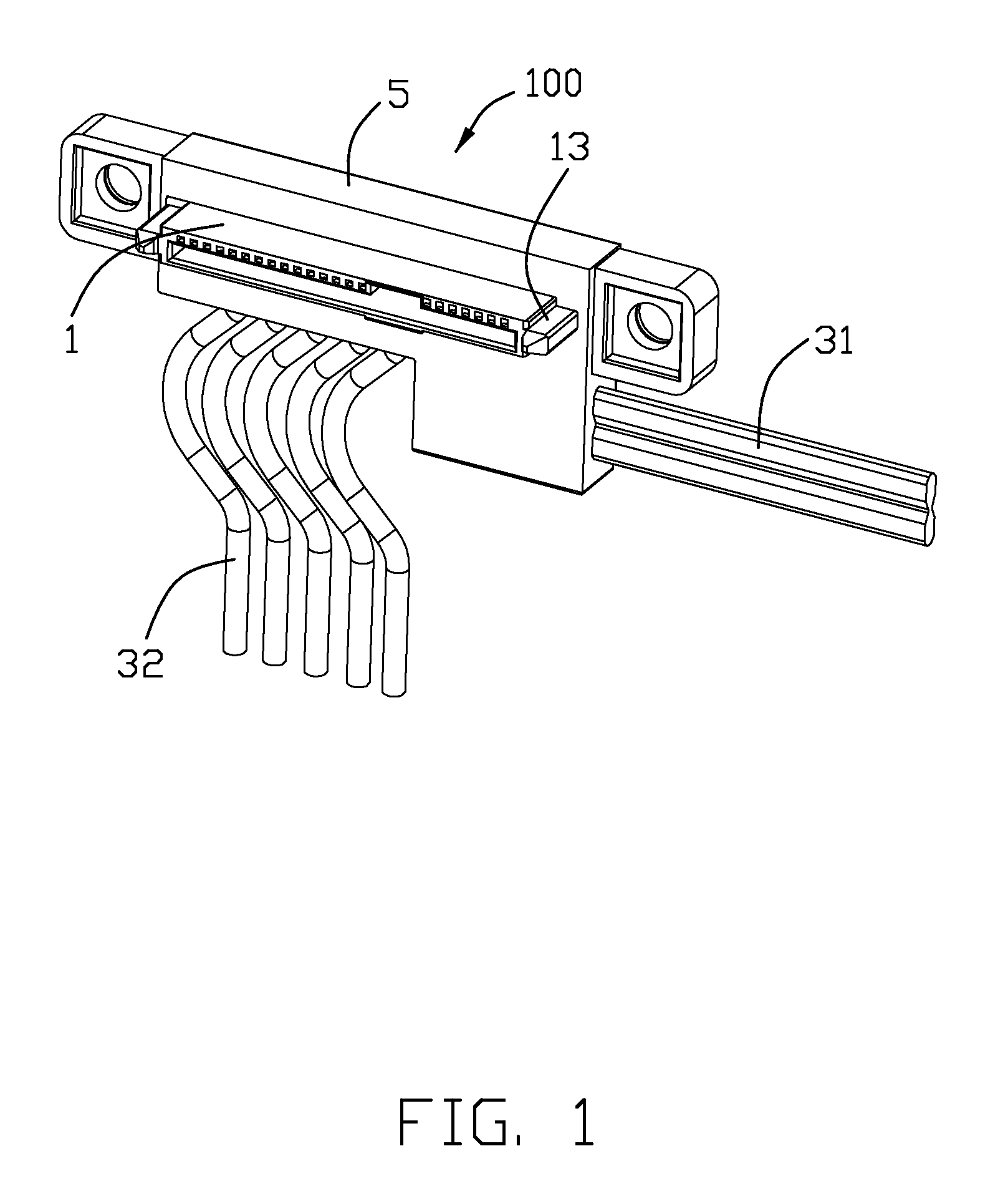
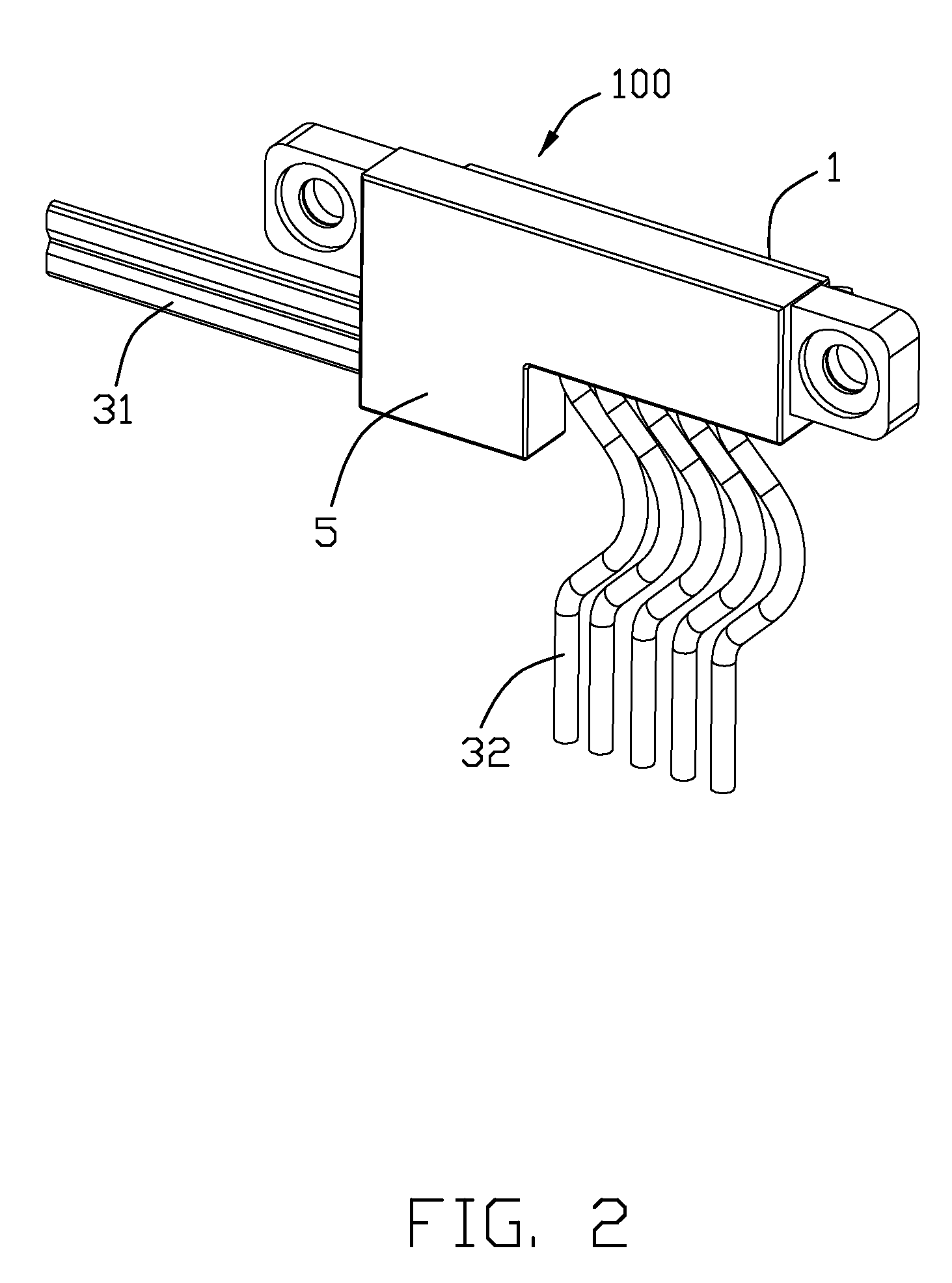
[0023]Referring to FIG. 1 and FIG. 4, a plug connector 100 of the first embodiment in accordance with the present invention comprises an insulative housing 1, a plurality of contacts 2 housed in the insulative housing 1, a plurality of wires 3 terminated to the contacts 2, a spacer 4 assembled to the insulative housing 1, a circuit board 6 positioned behind the spacer 4 and electrically connecting with the contacts 2 and the wires 3, and a cover 5 over-molded with the insulative housing 1.

[0024]Referring to FIGS. 1-5, the insulative housing 1 comprises an elongated base portion 10 and a mating portion 12 extending forwardly from a center of the base portion 10 along a mating direction of the plug connector 100, that is the first direction. The base portion 10 defines a first opening 14 and a second opening 15 recessed forwardly from a rear surface 102 thereof. A first leading portion ...


PUM


Abstract

A plug connector (100) includes an insulative housing (1) including a base portion (10) and a mating portion (12) extending from the base portion in a first mating direction, a number of contacts (2) received in the insulative housing, a circuit board (6) with a plurality of through holes (620) therein, and a number of wires (3) comprising a number of signal wires (31) and a number of power wires (32) respectively electrically connecting with the contacts. The contacts comprise a number of signal contacts (23) and a number of power contacts (21), the signal contacts are soldered with the circuit board. The signal wires are flatly soldered on the circuit board, the power wires are soldered with the contacts directly or electrically connected with the contacts by the circuit board. The signal wires are arranged to extend laterally along a second direction perpendicular to a first mating direction, the power wires are arranged to extend along a third direction perpendicular to the second direction.

Description

BACKGROUND OF THE INVENTION[0001]1. Field of the Invention[0002]The present invention generally relates to a plug connector, and more particularly to a plug connector in accordance with SAS (Serial Attached SCSI; Serial Attached Small Computer System Interface) or Serial ATA standard.[0003]2. Description of Related Art[0004]Computers are widely used in different fields today. Each computer is equipped a hard disk drive (HDD) for storing data. When the computer work, a Central Processing Unit (CPU) thereof continuously accesses the hard disk drive to retrieve data from the hard disk or store data to the hard disk drive. For compatibility, the interfaces of the hard disk drive are standardized. There is at least two or three existing standards, typically the SCSI (Small Computer System Interface) and ATA (Advanced Technology Attachment) standards in the last decade.[0005]Serial Attached SCSI is developed from parallel SCSI. Besides the advantages of higher signal transmission speed, t...

Claims


Application Information

Patent Timeline
Patent Type & Authority Patents(United States)
IPC IPC(8): H01R12/24
CPCH01R9/032H01R12/725H01R24/62H01R2107/00H01R13/65912
Inventor SU, PING-SHENGFAN, HONG-LEI
Owner HON HAI PRECISION IND CO LTD
Learn More