Industrial robot

a robot and industrial technology, applied in the field of industrial robots, can solve the problems of poor accessibility, high cost, and high cost, and achieve the effects of reducing the dimensions of the wrist housing, and facilitating the accessibility of the robot arm

Active Publication Date: 2010-10-05
ABB (SCHWEIZ) AG
View PDF16 Cites 10 Cited by
  • Summary
  • Abstract
  • Description
  • Claims
  • Application Information

AI Technical Summary

Benefits of technology

[0022]One advantage of the invention is that a compact wrist housing is obtained. A compact wrist housing facilitates the accessibility for a robot arm in small and narrow working spaces while at the same time the cabling does not physically encroach upon the operating space. It is thus important that the motors in the wrist housing be placed so that the dimensions of the wrist housing are minimized.
[0023]According to a preferred embodiment, the motors are placed in a common plane on both sides of the duct. With this embodiment, the length of the wrist housing is minimized. The turning radius of the wrist housing is limited by the location of the two motors. For a wrist housing designed according to the invention, this results in a physically large dimension but a reduced operating space.
[0024]According to another preferred embodiment, the motors are placed in a common plane on the same sides of the duct. Admittedly, this embodiment results in a longer wrist housing but permits the wrist housing to be optimized to operate in narrow passages.
[0025]The mechanics of a wrist housing according to the invention is arranged for the purpose of achieving a long service life and good mobility. The space in the wrist housing is limited and, in addition, the motors comprised therein require space. Motors and gears are arranged in the wrist housing in such a way as to accommodate internally disposed process cabling.
[0026]Since an industrial robot with a robot arm according to the present invention has process cabling disposed internally, such a robot has a well-defined outer contour that is simple to define graphically. An efficient simulation of such an industrial robot in a virtual computer environment is simpler to perform than of an industrial robot with a robot arm equipped with external process cabling. This is utilized, for example, to visualize stages of the operation or to control the industrial robot.
[0027]Advantageous further developments of the invention will become clear from the following description and claims.

Problems solved by technology

The longer and thicker a wrist housing is, the worse will be the accessibility.
Process cabling is space-demanding and stiff and is often disposed outside of the robot.
Process cabling that is disposed outside of the robot is easily subjected to impacts and extreme bending.
Such cables make it difficult to access and perform work in narrow spaces.
Motors and gears are thus located in such a way as to make it impossible to dispose the process cabling internally.
However, this publication only concerns motor cabling.
However, this publication does not describe how the drive motors for the wrist and the drive pulley are placed.
However, this publication only concerns the arrangement of cabling in the interior of a robot arm.

Method used


Image

  • Industrial robot
  • Industrial robot
  • Industrial robot

Examples


Embodiment Construction

[0033]The following description relates both to the method and to the device.

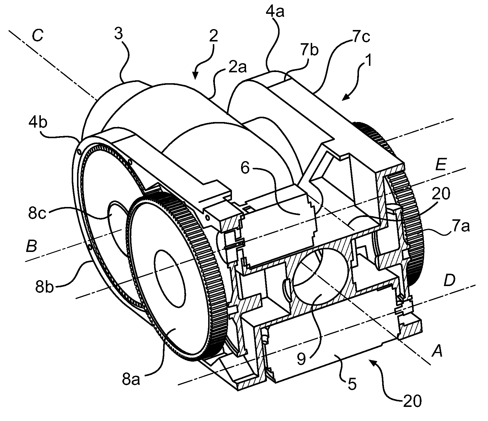
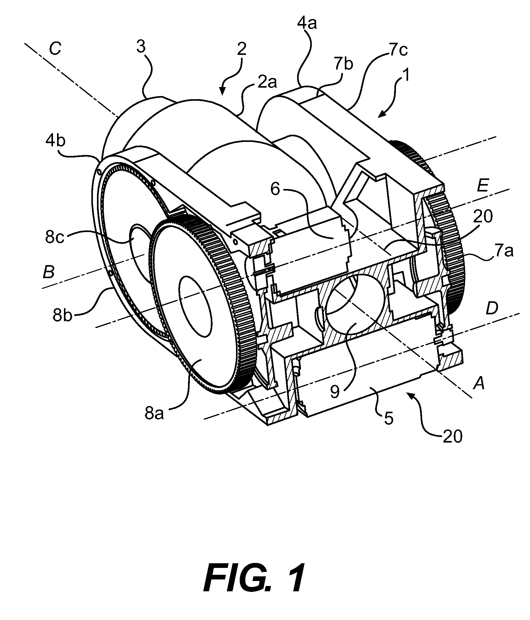
[0034]FIG. 1 shows a perspective view of the outer part of the second robot arm of an industrial robot (not shown in its entirety) of the previously described type. The outer part of the second robot arm comprises a wrist housing 1. The wrist housing supports a wrist 2 and a turn disc 3. The wrist housing 1 comprises a fork comprising two fork elements 4a, 4b. The wrist 2 comprises a sheath part 2a comprising two lugs. The wrist is connected to the wrist housing 1 with said lugs via said fork elements. The wrist housing further comprises a first drive unit comprising a first motor 5 and a first driving rope 7, comprising a first gear means 7a, 7b and a first torque transmission member 7c. The wrist housing also comprises a second drive unit with a second motor 6 and a second driving rope 8, comprising a second gear means 8a, 8b and a second torque transmission member 8c. In addition, the wrist housing compr...


PUM


Abstract

A robot arm for an industrial robot. The robot arm includes a wrist housing, a wrist, and a turn disc. The wrist is rotatably connected to the wrist housing and the turn disc is rotatably connected to the wrist. A first motor drives the wrist and a second motor drives the turn disc. A first driving rope transmits the motor rotation to the wrist, and a second driving rope transmits the motor rotation to the drive pulley.

Description

TECHNICAL FIELD[0001]The present invention relates to an industrial robot. More precisely, the invention relates to a robot arm in such an industrial robot. The robot arm comprises a wrist housing, a wrist and a turn disc. The turn disc is rotatable relative to the centre axis of the wrist. The wrist and the rotating movements of the turn disc are driven by drive units comprised in the robot arm. In particular, the invention relates to a wrist housing that supports a wrist.BACKGROUND ART[0002]An industrial robot is composed of interconnected robot parts such as, for example, a stand, robot arms, an arm housing, a wrist and a turn disc. Two adjoining robot parts are connected to each other so as to be rotatable in relation to each other around an axis of rotation or are linearly displaceable in relation to each other.[0003]An embodiment of an industrial robot according to the prior art comprises a stationary foot, which is mounted to a base. The foot supports a stand that is rotatabl...

Claims


Application Information

Patent Timeline
Patent Type & Authority Patents(United States)
IPC IPC(8): B25J17/02B25J9/10B25J19/00
CPCB25J9/102B25J17/0283B25J19/0029Y10T74/20317Y10T74/20311Y10T74/20323Y10T74/20335
Inventor FORSLUND, KARL-ERIKTHYSELIUS, LEGAL REPRESENTATIVE, ANNIKAKULLBORG, OVE
Owner ABB (SCHWEIZ) AG
Why Eureka
Try Eureka