

Process for concentrated biomass saccharification
a technology of biomass and concentrated biomass, which is applied in the direction of biofuels, fermentation, etc., can solve the problems that the saccharification of biomass at this high biomass concentration in an economically feasible reactor system is difficult to achieve, and the high sugar yield of biomass saccharification is difficult to achiev
- Summary
- Abstract
- Description
- Claims
- Application Information
AI Technical Summary
Problems solved by technology
Method used
Image

Examples
example 1
Saccharification of Pretreated Biomass with and without Stirring
[0114]Two runs (#25 and 26) were conducted with milled pretreated biomass at 50° C., pH=5.5 with about 20% DWB (Dry Weight of Biomass) loading. The biomass used in these runs was a blend of three batches of pretreated corn cobs that were size reduced to about 1 mm. One batch, labeled HT-4, was prepared in the steam gun reactor, described above, by treating the fractured corn cobs with 4 g NH3 per 100 gram of dry weight biomass and steam at 145° C. for 20 minutes. The other two batches were prepared in the Barrel Piston reactor, described above, by treating the corn cobs with 6 g NH3 per 100 gram of dry weight biomass and steam at 145° C. for 10 minutes. The blend of these three batches of pretreated biomass was ground in a Waring commercial blender and screened through a 1.1 mm screen, before using in the saccharification experiments.
[0115]The runs were conducted in 500 mL glass jacketed cylindrical reaction vessels, de...
example 2
Saccharification of Pretreated Biomass with Varying Initial Size
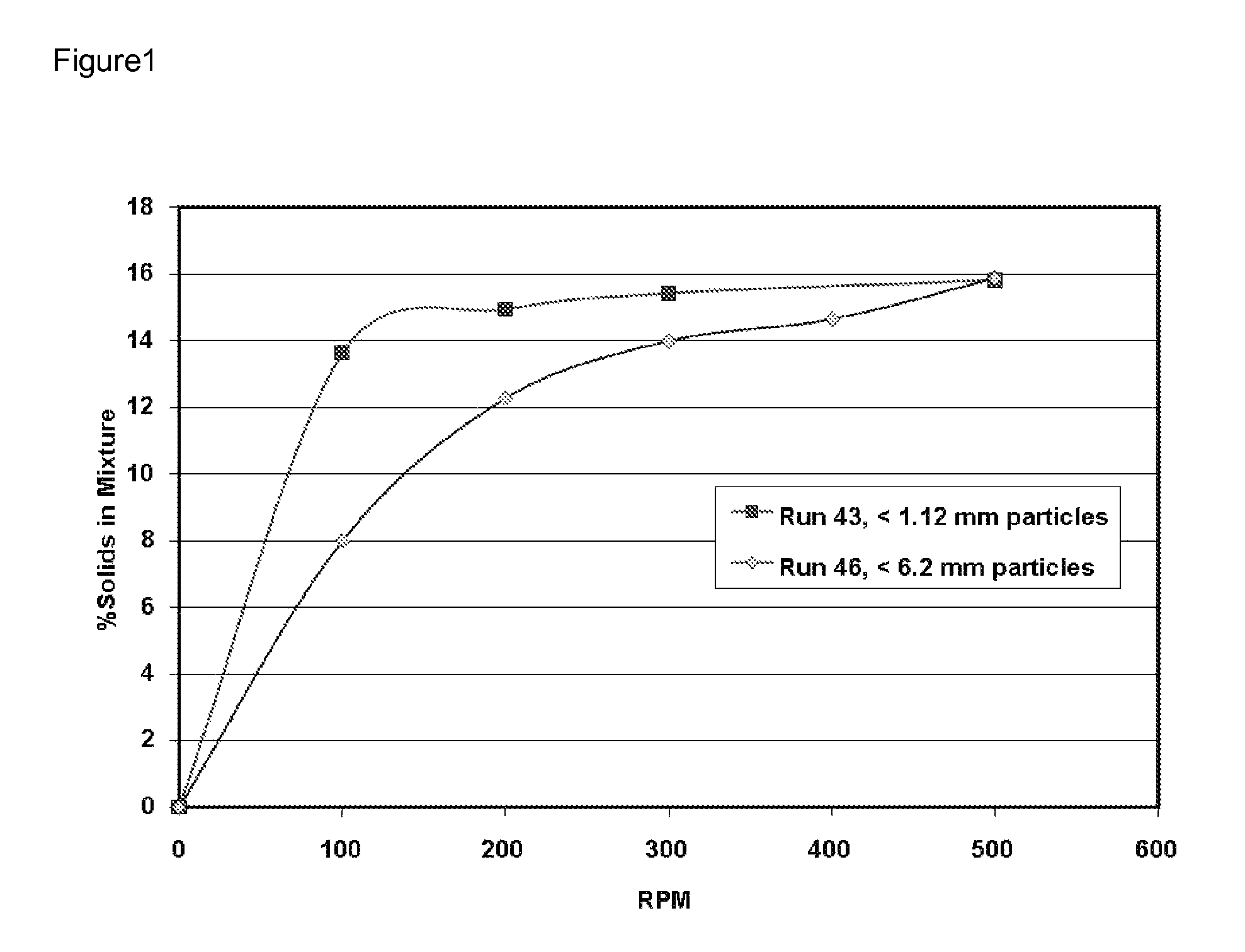
[0120]Runs 50-52 and 64-65 were conducted with pretreated biomass milled to different sizes. The pretreated biomass was prepared from crushed corn cobs that were hammermilled and screened through a ½ inch screen. They were treated in the Jaygo Reactor, described in General Methods, with 4 g NH3 per 100 gram of dry weight biomass and steam at 145° C. for 20 minutes. This pretreated corn cob biomass was labeled Jaygo-10. Before saccharifying, the pretreated corn cobs were further milled in multiple steps and screened through appropriate size screens to prepare the biomass for each saccharification run. The screen size used for preparing samples for each run is shown in Table 2 below.
[0121]Runs 50 and 51 were conducted in 2-L reactors and Runs 52, 64 and 65 were conducted in 0.5 L reactors. In all cases, de-ionized water was used as the reaction heel. Pretreated biomass was added to make hydrolysates of about 12% DWB in Ru...
example 3
Liquefaction of Biomass During Enzymatic Saccharification
[0126]Run 52, described above, was also used to determine the changes in particle size distribution and the liquefaction of biomass as the saccharification process continued. The particle size distributions were measured for the initial milled pretreated corn cob biomass and for the hydrolysate after 6 and 72 hours.
[0127]
TABLE 4Reduction of particle size distribution duringsaccharification - Run 52Hydrolysate d-50Hydrolysate d-95Run Timemicrometermicrometer0 hr177.51020.86 hr38.9163.572 hr 17.1136
This result clearly indicated that enzymatic saccharification reduces the size distribution of the solid particles, thus causing liquefaction of solids, opening room for additional solids to be added to the hydrolysate.
PUM
| Property | Measurement | Unit |
|---|---|---|
| yield stress | aaaaa | aaaaa |
| concentration | aaaaa | aaaaa |
| temperature | aaaaa | aaaaa |
Abstract
Description
Claims
Application Information