Boat propulsion unit

a propulsion unit and boat technology, applied in the direction of marine propulsion, propulsive elements, vessel construction, etc., can solve the problems of difficult to achieve the acceleration performance and the maximum speed to reach and it is difficult to improve the acceleration performance at a low speed, and achieve the maximum speed and acceleration performance to achieve the level desired by users. , to achieve the effect of inhibiting the occurrence of the loss of driving energy of the engin

Active Publication Date: 2010-10-12
YAMAHA MOTOR CO LTD
View PDF4 Cites 8 Cited by
  • Summary
  • Abstract
  • Description
  • Claims
  • Application Information

AI Technical Summary

Benefits of technology

[0008]In order to overcome the problems described above, preferred embodiments of the present invention provide a boat propulsion unit arranged to allow a performance of both the acceleration and the maximum speed to approach a level desired by a user and to inhibit the occurrence of the loss of the driving energy of the engine.
[0010]As described above, the boat propulsion unit according to this preferred embodiment provides a variable speed mechanism portion arranged to transmit a driving force generated by an engine to a propeller such that the driving force has its speed changed by at least a low reduction ratio and a high reduction ratio. In this way, by configuring the variable speed mechanism portion so that it can transmit the driving force generated by the engine to the propeller such that the driving force has its speed changed by a low reduction ratio, the acceleration performance at a low speed can be improved. Moreover, by configuring the variable speed mechanism portion so that it can transmit the driving force generated by the engine to the propeller such that the driving force has its speed changed by a high reduction ratio, the maximum speed can be increased. As a result, it is possible to provide both the performance of acceleration and maximum speed to approach a level desired by a user. Moreover, an oil tank provided on the outside of the first housing arranged to retain oil to be supplied to the first housing and an oil lubrication route arranged to supply oil in the oil tank to the first housing and collecting the oil supplied to the first housing in the oil tank are provided. In this way, by collecting the oil supplied to the first housing in the oil tank provided on the outside of the first housing, oil retention in the first housing can be prevented. This prevents the variable speed mechanism portion in the first housing from being soaked in the oil, thereby preventing the gear and the like of the variable speed mechanism portion from being driven while soaked in the oil. As a result, an occurance of the gear being prevented from rotating due to viscosity of the oil and the like can be prevented, so that a loss of the driving energy of the engine can be minimized.

Problems solved by technology

However, in the boat propulsion machine (boat propulsion unit) disclosed in JP-A-Hei 9-263294, when the reduction ratio of the power transmission mechanism is configured so that the maximum speed becomes large, it is difficult to improve the acceleration performance at a low speed.
Conversely, when the reduction ratio of the power transmission mechanism is configured so that the acceleration performance at a low speed is improved, it is difficult to increase the maximum speed.
That is, in the boat propulsion machine disclosed in the JP-A-Hei 9-263294, it is difficult to achieve both a performance of the acceleration and the maximum speed to approach a level desired by a user.
Consequently, the gear is prevented from rotating due to viscosity of the oil and the like, so that there is a problem that the loss of the driving energy of the engine occurs.

Method used


Image

  • Boat propulsion unit
  • Boat propulsion unit
  • Boat propulsion unit

Examples


first preferred embodiment

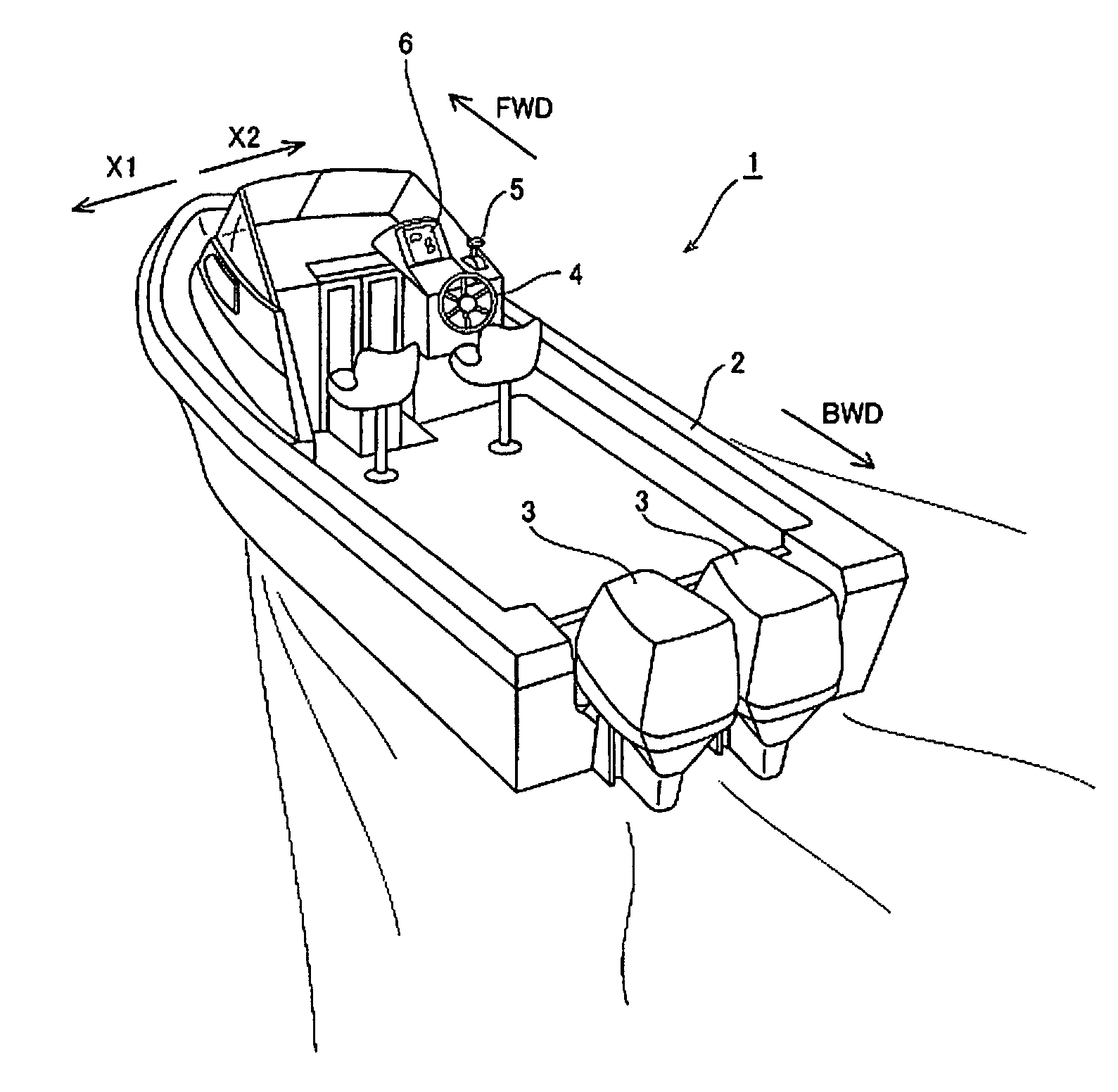
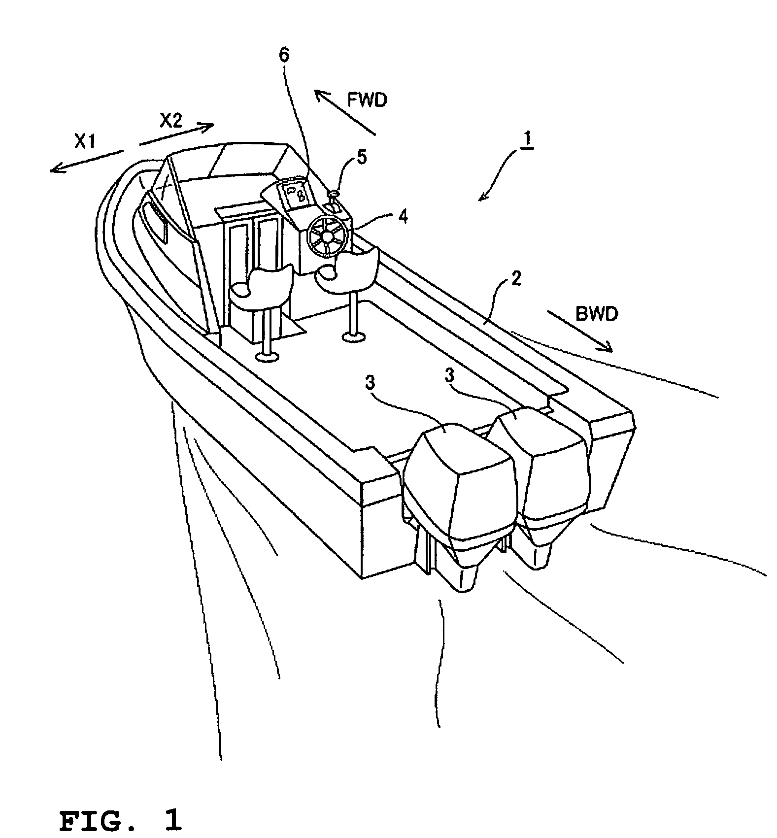
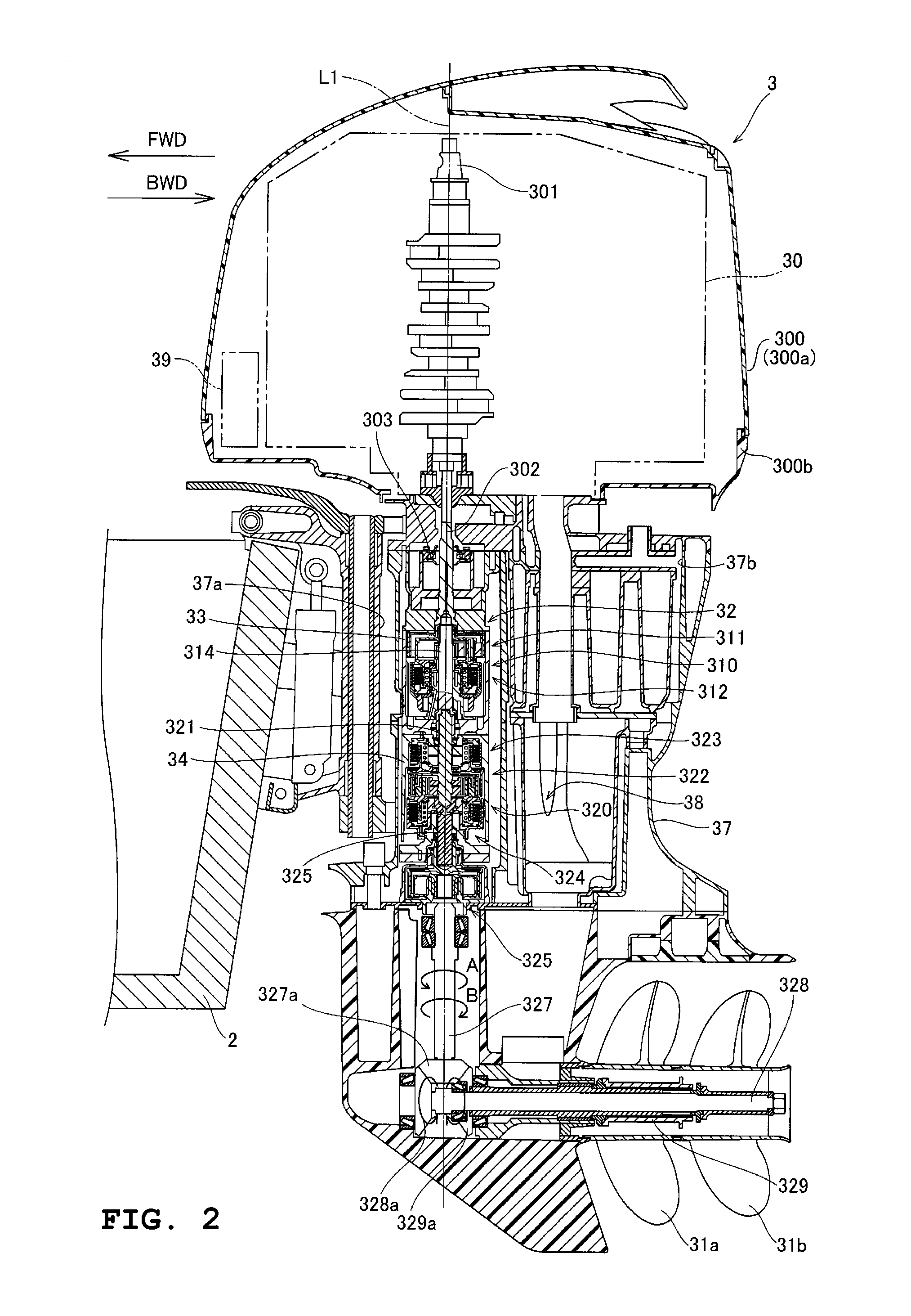
[0019]FIG. 1 is a perspective view showing a boat on which an outboard motor according to the first preferred embodiment of the present invention is mounted. FIGS. 2 through 4 are drawings providing a detailed explanation of the outboard motor according to the first preferred embodiment shown in FIG. 1. In the figures, the “FWD” direction indicates the forward direction of the boat, and the “BWD” direction indicates the backward direction of the boat. Initially, with reference to FIGS. 1 through 4, the configuration of an outboard motor 3 mounted on a boat 1 according to the first preferred embodiment will be explained.

[0020]As shown in FIG. 1, the boat 1 according to the first preferred embodiment includes a hull 2 preferably floating on the water, two outboard motors 3 mounted on a rear portion of the hull 2 and arranged to drive the hull 2, a steering portion 4 arranged to steer of the hull 2, a control lever portion 5 which is provided adjacent to the steering portion 4 and capa...

second preferred embodiment

[0069]FIG. 5 is a drawing explaining the configuration of an oil lubrication route of an outboard motor according to the second preferred embodiment of the present invention. Hereinafter, with reference to FIG. 5, the configuration of the outboard motor according to the second preferred embodiment of the present invention will be explained in detail. This second preferred embodiment describes an example of a configuration in which the oil retained in the lower housing 34 is suctioned to the oil tanks 35a and 35b without providing an oil pump that suctions the oil retained in the lower housing 34 to the oil tanks 35a and 35b, unlike the first preferred embodiment.

[0070]As shown in FIG. 5, in the second preferred embodiment, since the oil pump that suctions the oil retained in the lower housing 34 to the oil tanks 35a and 35b is not provided, unlike in the first preferred embodiment, the upper variable speed portion 310 does not include a spur gear arranged to drive the oil pump.

[0071...

third preferred embodiment

[0078]FIG. 6 is a drawing explaining the configuration of an oil lubrication route of an outboard motor according to the third preferred embodiment of the present invention. Hereinafter, with reference to FIG. 6, the configuration of the outboard motor according to the third preferred embodiment of the present invention will be explained in detail. In this third preferred embodiment, a description will be made with respect to an example in which two oil pumps which are an oil pump 364 that supplies oil to the solenoid valves 309a, 309b, and 309c and an oil pump 362 that supplies the oil to the variable speed mechanism portion 32 are provided, unlike the first and second preferred embodiments.

[0079]As shown in FIG. 6, an ECU (Engine Control Unit) 361 arranged to control the rotation speed of the engine 30, the gear shift timing of the variable speed mechanism portion 32, and the like is provided on the outboard motor according to the third preferred embodiment of the present inventio...


PUM


Abstract

An outboard motor includes a variable speed mechanism portion arranged to transmit a driving force to propellers such that the driving force is changed in its speed by a low reduction ratio and a high reduction ratio, an upper housing that houses the variable speed mechanism portion, oil tanks provided on the outside of the upper housing and arranged to retain oil to be supplied to the upper housing, and an oil lubrication route arranged to supply oil in the oil tanks to the upper housing and to collect the oil supplied in the upper housing in the oil tanks. The above arrangement provides a boat propulsion unit capable of allowing both a performance of acceleration and a maximum speed to approach a level desired by a user and to prevent the occurrence of a loss of the driving energy of an engine.

Description

BACKGROUND OF THE INVENTION[0001]1. Field of the Invention[0002]The present invention relates to a boat propulsion unit. More specifically, the present invention relates to a boat propulsion unit having an engine.[0003]2. Description of the Related Art[0004]Conventionally, a boat propulsion machine having an engine (boat propulsion unit) is known (for example, see JP-A-Hei 9-263294). JP-A-Hei 9-263294 discloses a boat propulsion machine having an engine and a power transmission mechanism for transmitting the driving power of the engine to a propeller by a specified fixed reduction ratio. This boat propulsion machine transmits the driving power of the engine directly to the propeller through the power transmission mechanism, and the propeller speed increases in proportion with an increase in the engine speed.[0005]However, in the boat propulsion machine (boat propulsion unit) disclosed in JP-A-Hei 9-263294, when the reduction ratio of the power transmission mechanism is configured so...

Claims


Application Information

Patent Timeline
Patent Type & Authority Patents(United States)
IPC IPC(8): B63H20/14
CPCB63H23/30
Inventor FUKUOKA, YOSHIHITO
Owner YAMAHA MOTOR CO LTD
Why Eureka
Try Eureka