Testing method for LED module

a technology of led modules and test methods, applied in the field of testing methods, can solve the problems of deteriorating light-emitting efficiency of led lamps, inability to improve test efficiency, and moving each of light-emitting diodes or integrating sphere measurement devices, so as to save time for moving each of light-emitting diodes and improve test efficiency.

Inactive Publication Date: 2010-10-12
HIGH POWER LIGHTING CORP
View PDF2 Cites 29 Cited by
  • Summary
  • Abstract
  • Description
  • Claims
  • Application Information

AI Technical Summary

Benefits of technology

[0010]In comparison with prior art, the present invention has solved the problem that the light-emitting diodes conventionally have to be positioned on a one-dimensional or two-dimensional displacing means to make each of the light-emitting diodes to be aligned with the integration detector for testing. According to the present invention, the integrati

Problems solved by technology

If one of the light-emitting diodes suffers damage to fail to emit light, the light-emitting efficiency of this lamp is deteriorated.
Thus, it is an important issue to guarantee the yield in manufacturing light-emitting diodes.
However, in practice, such a testing method still has a problem that each of the light-emitting di

Method used


Image

  • Testing method for LED module
  • Testing method for LED module
  • Testing method for LED module

Examples


Embodiment Construction

[0019]The detailed description and technical contents of the present invention will be explained with reference to the accompanying drawings. However, the drawings are illustrative only but not used to limit the present invention.

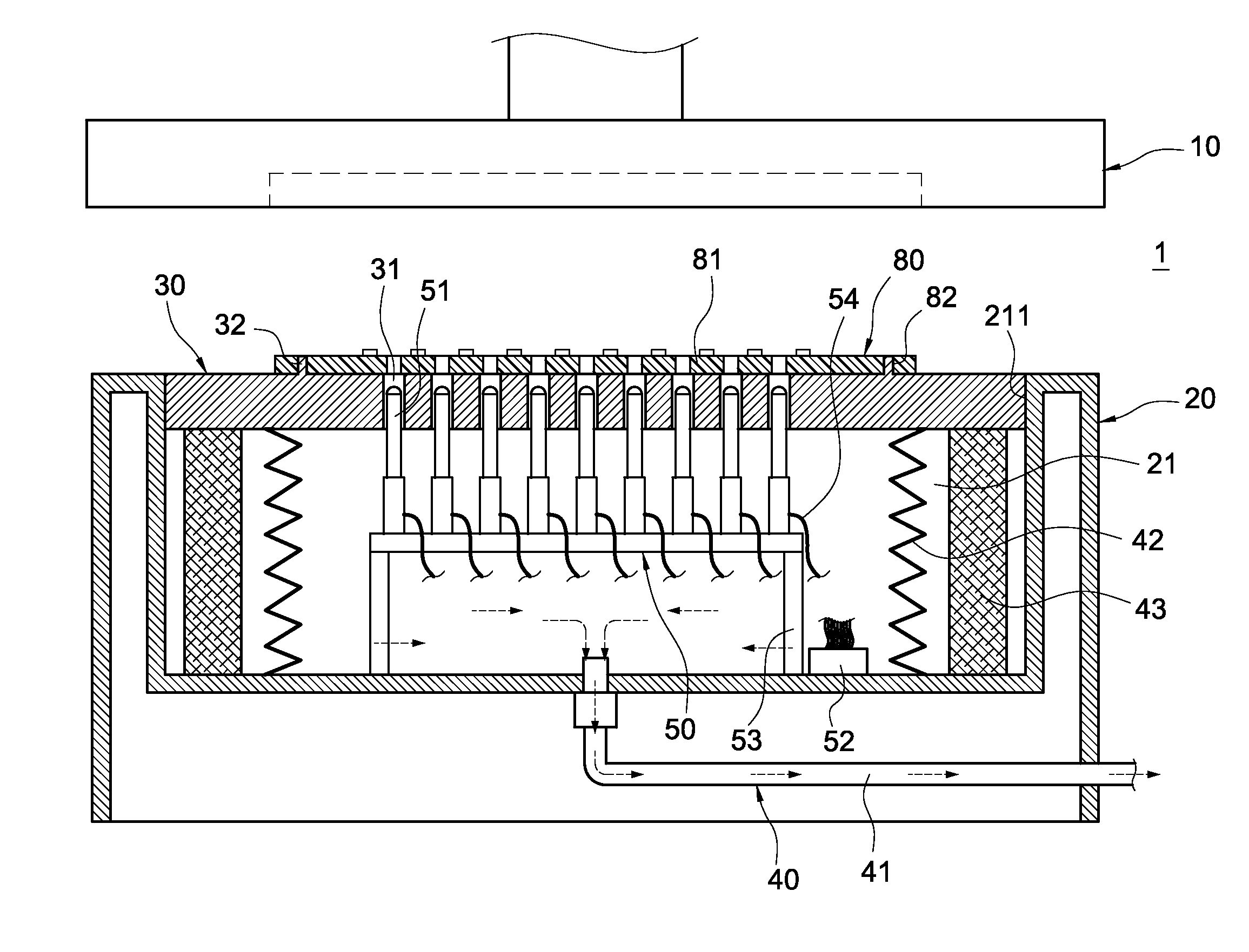
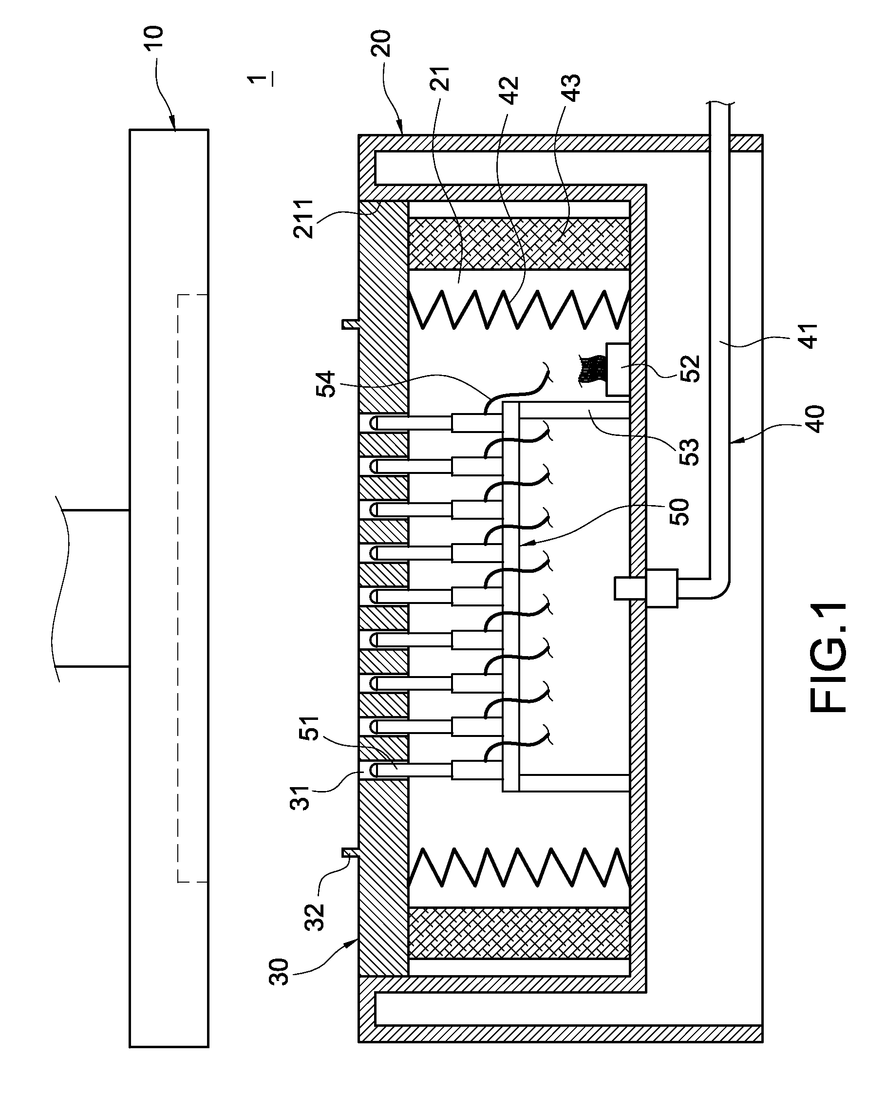
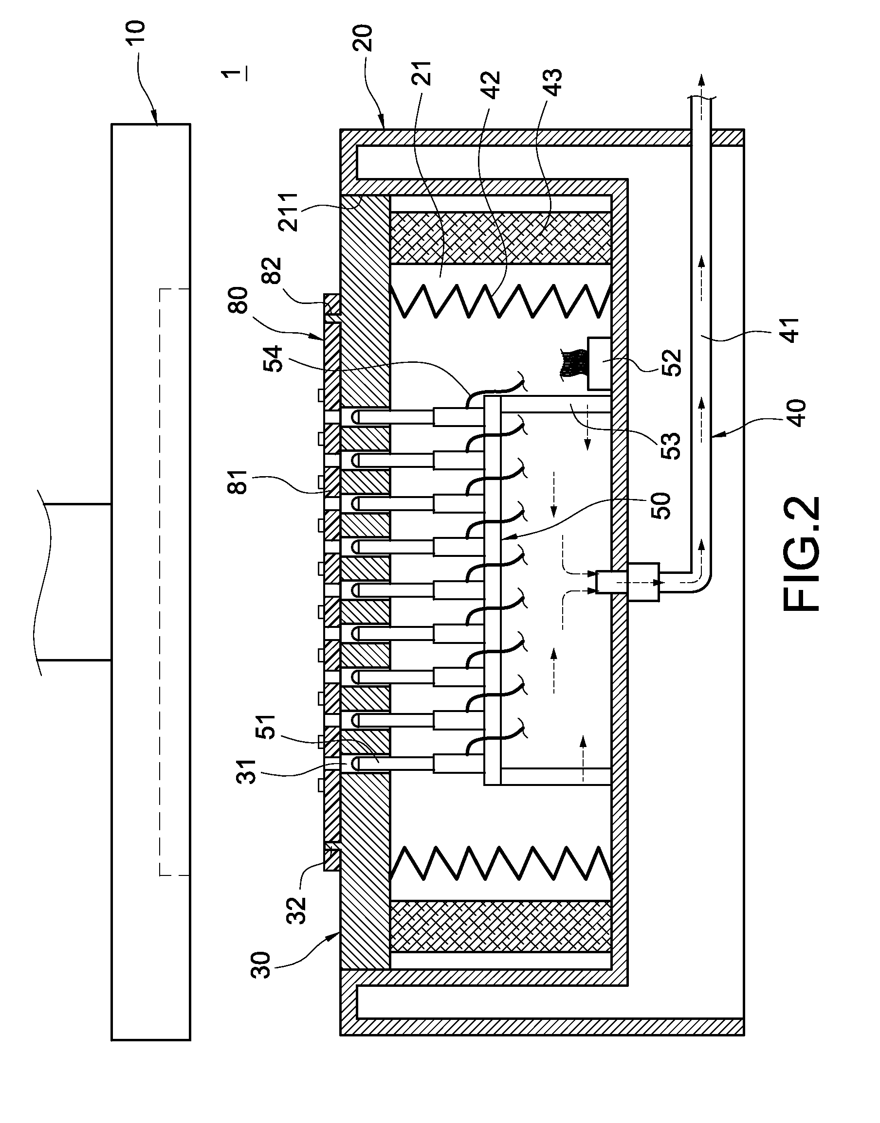
[0020]Please refer to FIGS. 1 to 3. FIG. 1 is a cross-sectional perspective view showing the testing device of the present invention, FIG. 2 is a cross-sectional view (I) showing the operating state of the testing device of the present invention, and FIG. 3 is a cross-sectional view (II) showing the operating state of the testing device of the present invention. The present invention provides a testing method for a LED module 80. A plurality of light-emitting diodes 81 are arranged on the LED module 80. The testing device 1 used in this testing method includes an integration detector 10, a casing 20, a supporting plate 30, a transmission means 40 and an electrically connecting means 50.

[0021]The integration detector 10 is arranged to correspond to the LED m...


PUM


Abstract

A testing method for a LED module and its associated elements includes the steps of: providing a LED module on which a plurality of light-emitting diodes is arranged; providing an integration detector, and mounting it above the LED module; providing an electrically conducting means having a plurality of conductive terminals and an electronic signal connector electrically connected to the conductive terminals; electrically connecting the light-emitting diodes with the conductive terminals; using the electronic signal connector to change the ON/OFF states of the electrical signals of the light-emitting diodes and the conductive terminals; and detecting the photo-electrical properties of each light-emitting diode via the integration detector.

Description

BACKGROUND OF THE INVENTION[0001]1. Field of the Invention[0002]The present invention relates to a testing method, and in particular to a testing method for a LED module and its associated elements.[0003]2. Description of Prior Art[0004]Recently, light emitting diodes (LED) are widely used for illumination, such as in a flashlight, tail lamp or indicator of a motorcycle (automobile) and traffic light. The above-mentioned lamps are constituted of a plurality of light-emitting diodes. If one of the light-emitting diodes suffers damage to fail to emit light, the light-emitting efficiency of this lamp is deteriorated. Thus, it is an important issue to guarantee the yield in manufacturing light-emitting diodes.[0005]Therefore, after the light-emitting diodes are manufactured completely, they have to be tested before leave the factory, thereby guaranteeing their normal operation. The conventional testing device for LED is an integrating sphere measurement device. However, when the integra...

Claims


Application Information

Patent Timeline
IPC IPC(8): G01R31/302
CPCG01R31/2635H01L2224/48091H01L2224/73265H01L2924/00014
Inventor WEI, CHIH-HUNGWU, MING-CHANGHSU, CHIH-YANGWU, CHIH-LUNGJHENG, DING-YUAN
Owner HIGH POWER LIGHTING CORP
Why Eureka
Try Eureka