
System and method for identifying original design intents using 3D scan data

a technology of original design intents and scan data, applied in the field of reverse engineering 3d scan data, can solve the problems of difficult to determine from 3d scan data difficulty in retracing original design intents and their parameter values, and less precise and productive reverse engineering process

Active Publication Date: 2010-10-12
INUS TECH
View PDF6 Cites 23 Cited by
  • Summary
  • Abstract
  • Description
  • Claims
  • Application Information

AI Technical Summary

Benefits of technology

"The present invention provides a method and system for extracting and managing solid and surface modeling parameters from raw 3D scan data. This allows users to programatically segment and select a type of design intent from the 3D scan data, and calculate an approximate value for the selected design intent using the raw scan data. This results in a more efficient and accurate process for reverse engineering and modeling objects using 3D scan data."

Problems solved by technology

Unfortunately, the raw scan data captured by a 3D scanner during a reverse engineering process only represents a final geometry of the object.
The fact that the 3D scan data only represents a final geometry of the object makes it difficult to retrace the original design intents and their parameter values.
For example, it is difficult to determine from 3D scan data original design intents and their parameter values for features such as an extrusion 2D profile, a direction and distance, a revolving 2D profile, an axis and angle, a constant or varying filleting radii, a drafting plane and its angle, sweeping path curves, center lines of curved pipes, etc.
The inability to determine the original design intents leads to the reverse engineering process being less precise and productive.

Method used


Image

  • System and method for identifying original design intents using 3D scan data
  • System and method for identifying original design intents using 3D scan data
  • System and method for identifying original design intents using 3D scan data

Examples


Embodiment Construction

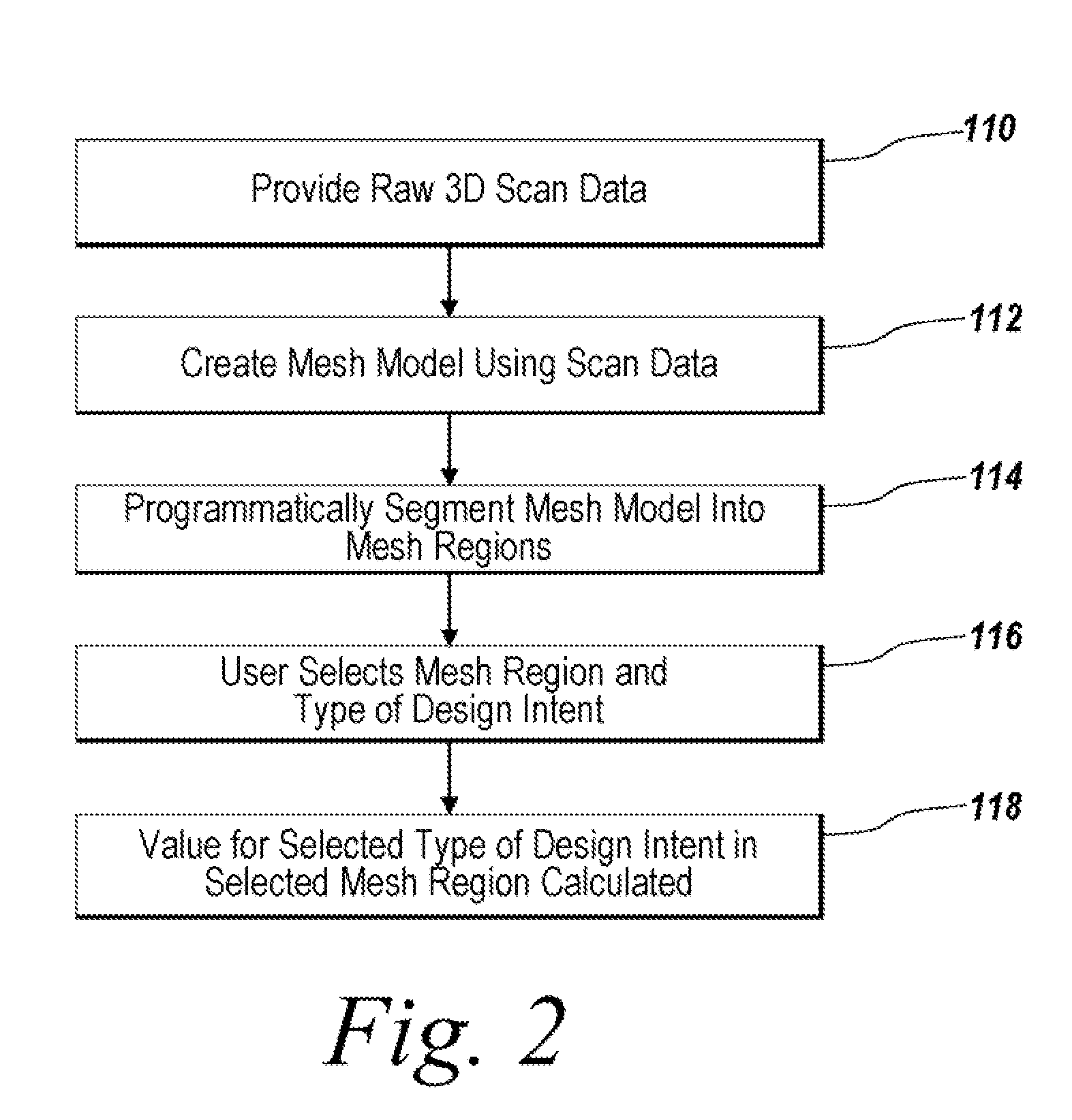
[0042]The illustrative embodiment of the present invention provides a user with tools to approximate original model design intents while reverse engineering a three-dimensional object from 3D scan data. An automated process allows a user to target particular mesh regions and specify the particular type of original design feature for which the user is interested in obtaining a parameter value. The present invention programmatically analyzes the underlying mesh data in order to infer the original design intent and present the user with a best estimation as to a value for the original design intent. The user is then able to use the approximation or modify it as required while creating solid model parts.

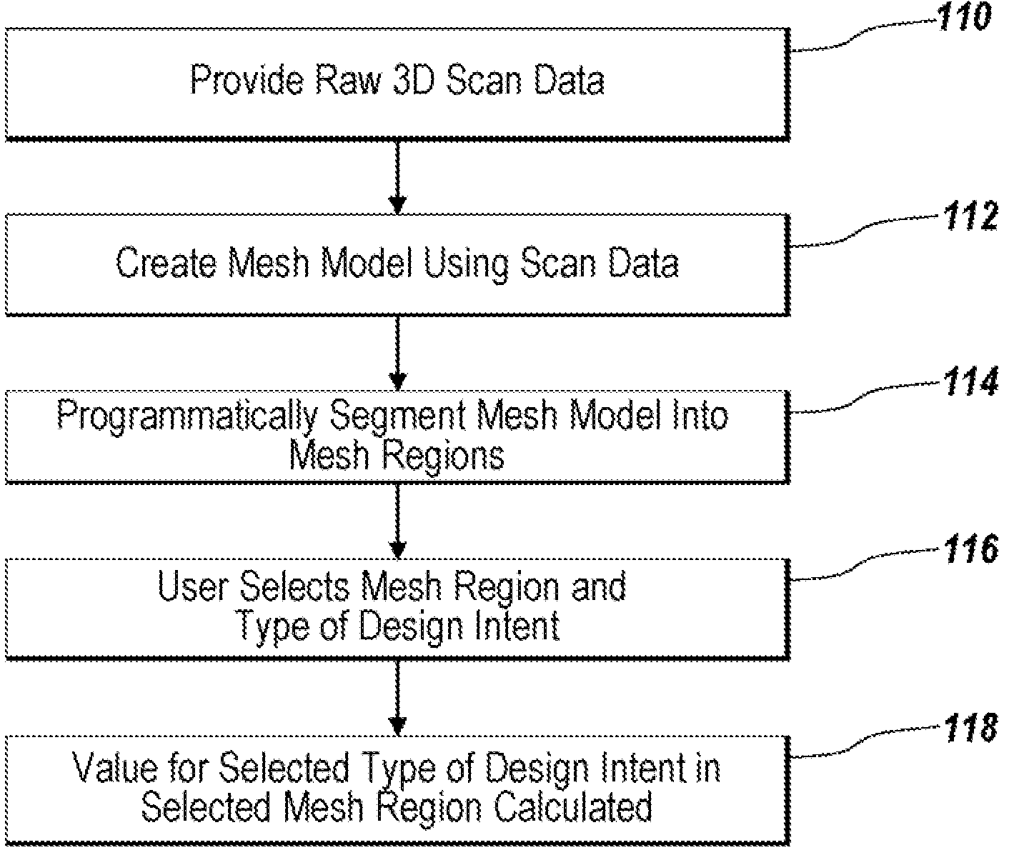
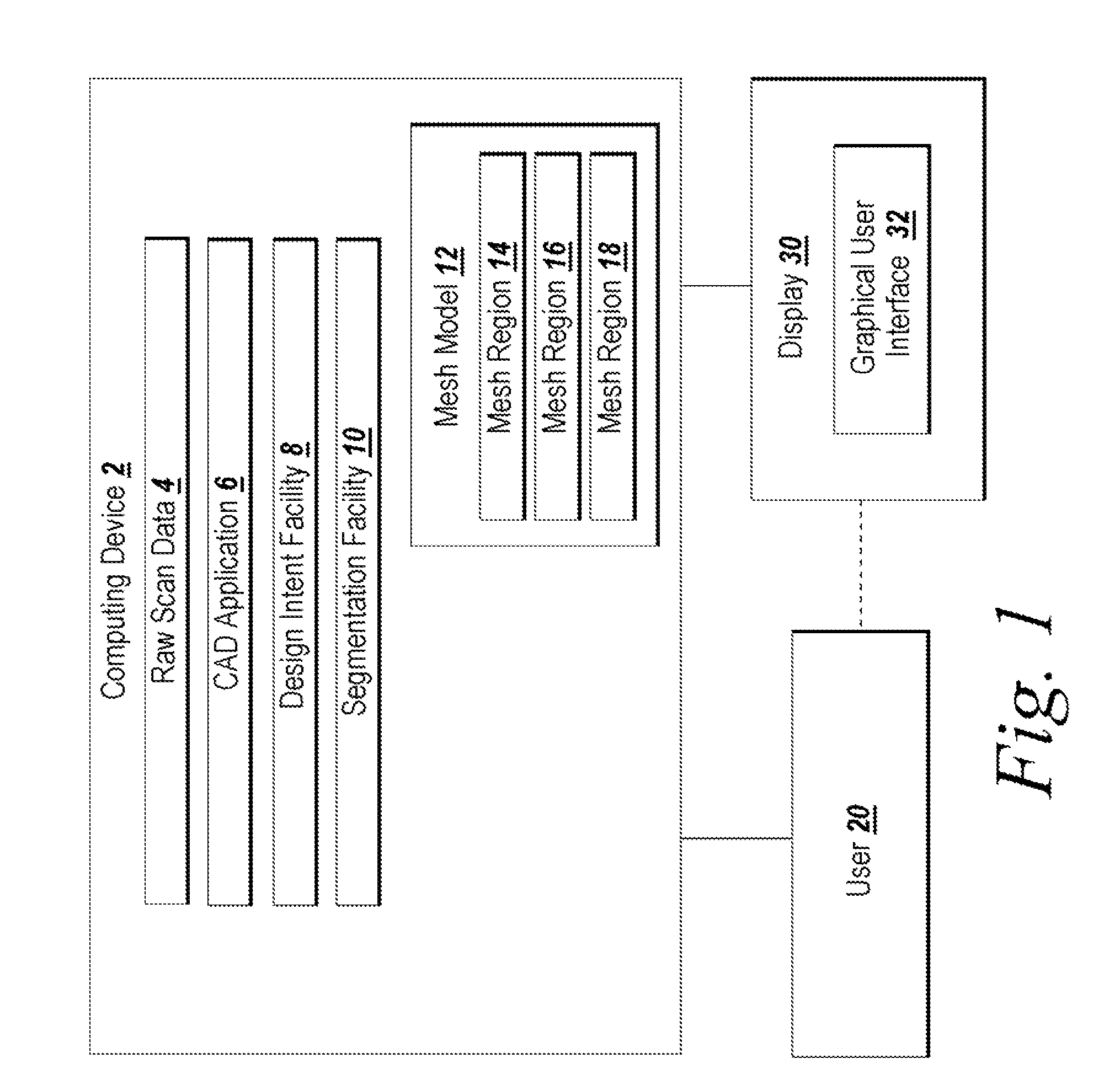
[0043]FIG. 1 depicts an environment suitable for practicing the illustrative embodiment of the present invention. A computing device 2 includes a collection of raw 3D scan data 4 for a scanned three-dimensional object. The raw 3D scan data 4 is collected from a three-dimensional scanner....


PUM


Abstract

Programmatic extraction and management of solid and surface modeling parameters from raw 3D scan data is discussed. An automated process reads raw 3D scan data and works in communication with a CAD system able to perform CAD part modeling. The user is provided with an automatic function to segment a mesh model (formed from the raw 3D scan data) into dozens of mesh regions. A graphical user interface is provided which enables a user to choose a type of the design intent along with the mesh regions from which the design intent is calculated. Each design intent is represented in a vector, a plane or a poly-line depending upon the type of design intent. In response to a user demand for the parameters of a modeling feature, a best approximation of the requested parameter value is calculated by processing the raw 3D scan data using a set of functions.

Description

FIELD OF THE INVENTION[0001]The illustrative embodiment of the present invention relates generally to CAD (Computer Aided Design) and more particularly to reverse engineering 3D scan data to identify original design intents during a part redesign process.BACKGROUND[0002]Computer Aided Design (CAD) applications are used to produce computer models of two and three dimensional objects as part of the production process for the actual physical device being modeled. The models frequently include multiple parts which must be individually designed. The designer of the model parts may use specialized modeling features in order to design the model parts. Exemplary modeling features (which may be referred to as design intents) include extrusion, revolving, shelling, filleting, sweeping, lofting, blending, embossing, pattern copying, etc. The design intents may be parameterized and the model designer frequently experiments with different parameter values for the design intents during the design...

Claims


Application Information

Patent Timeline
Patent Type & Authority Patents(United States)
IPC IPC(8): G06F17/50
CPCG06F17/50G06T17/20G06F30/00
Inventor BAE, SEOCKHOONLEE, DONGHOONYANG, CHANGYOON
Owner INUS TECH
Learn More