Disc player apparatus with upper and lower rollers for transporting and guiding a disc

a disc player and upper roller technology, applied in the field of disc player equipment, can solve the problems of unsatisfactory impact noise, springs that do not provide predetermined torque, and no consideration has been disclosed so far on the method of mounting the damper on the cas

Inactive Publication Date: 2010-10-12
SANYO ELECTRIC CO LTD +1
View PDF24 Cites 10 Cited by
  • Summary
  • Abstract
  • Description
  • Claims
  • Application Information

AI Technical Summary

Benefits of technology

[0020]A first object of the present invention is to provide a slot-in type disc player apparatus which is easy to assemble yet capable of giving a predetermined friction torque between the roller and the roller shaft.
[0021]A second object of the present invention is to eliminate the impact noise at the time of ejection in the slot-in type disc player apparatus.
[0022]A third object of the present invention is to provide a slot-in type disc player apparatus capable of ejecting the disc smoothly at the time of ejection.

Problems solved by technology

Conventionally, however, the urging spring requires a burdensome step to assemble, and depending on the way it is assembled, the spring does not provide the predetermined torque.
This has created a problem that during a disc ejecting operation after the turntable and the clamper are separated from each other, part of the disc hits a clamper arm which supports the clamper before the disc is sandwiched between the transporting roller and the guide roller, making an uncomfortable impact noise for example.
However, no consideration has been disclosed so far on the method for mounting the dampers on the case.
A poor positioning of the dampers on the case will cause the dampers to fall off.

Method used


Image

  • Disc player apparatus with upper and lower rollers for transporting and guiding a disc
  • Disc player apparatus with upper and lower rollers for transporting and guiding a disc
  • Disc player apparatus with upper and lower rollers for transporting and guiding a disc

Examples


Embodiment Construction

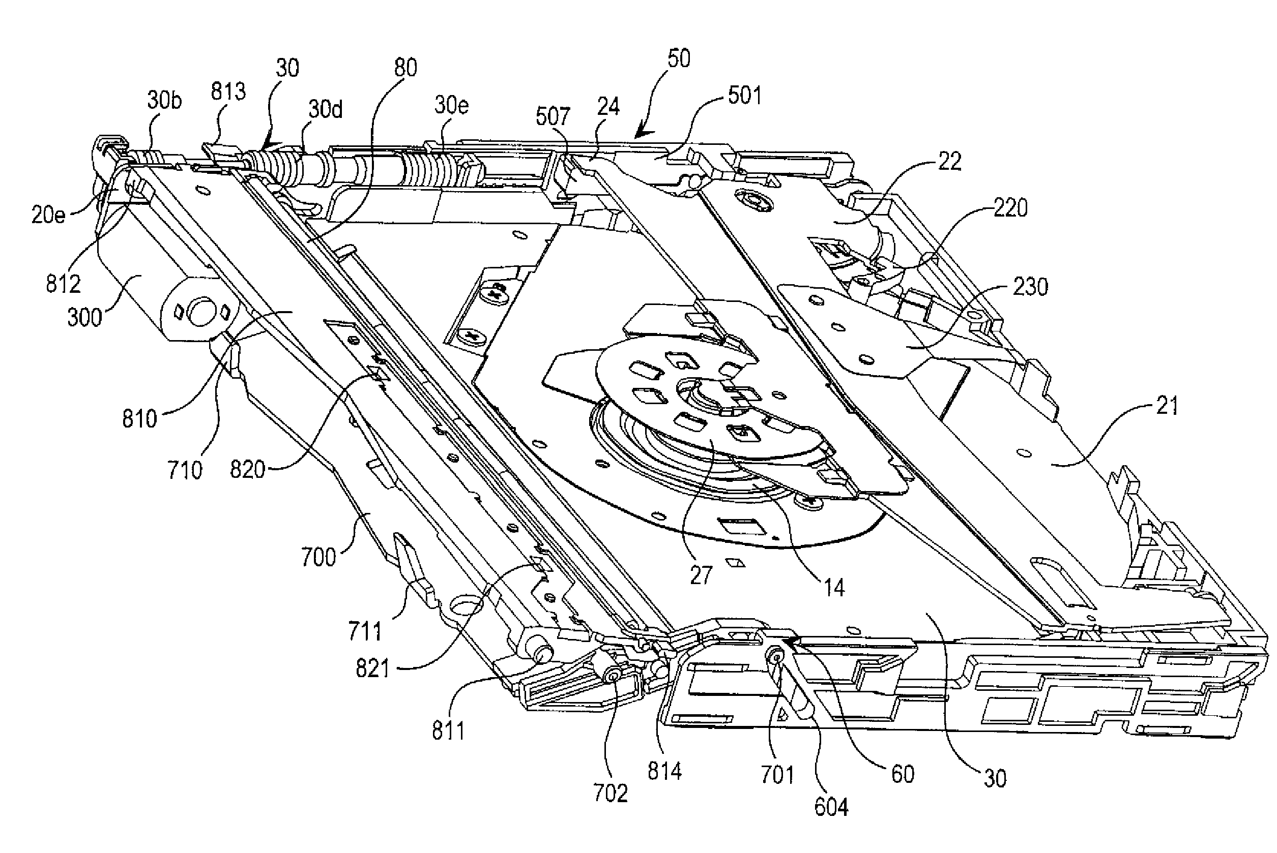
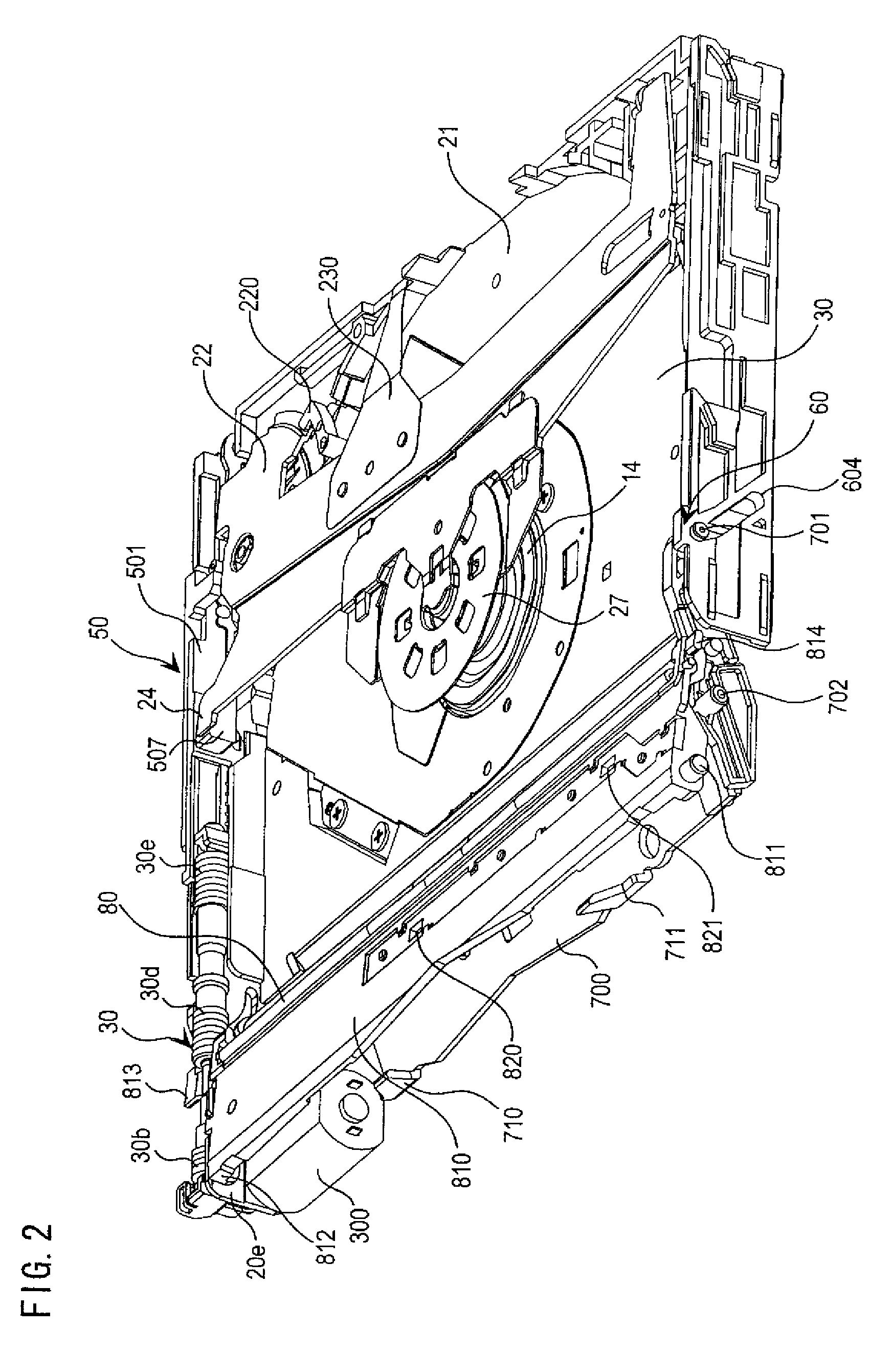
[0068]Hereinafter, an embodiment of the present invention will be described with reference to FIG. 1 through FIG. 24. In the following embodiment, the term front-end side means the side closer to the farthest end of a main body case 20, i.e. the side away from a disc insertion slot 12, whereas the term rear-end side refers to the side closer to the disc insertion slot 12 unless otherwise stated.

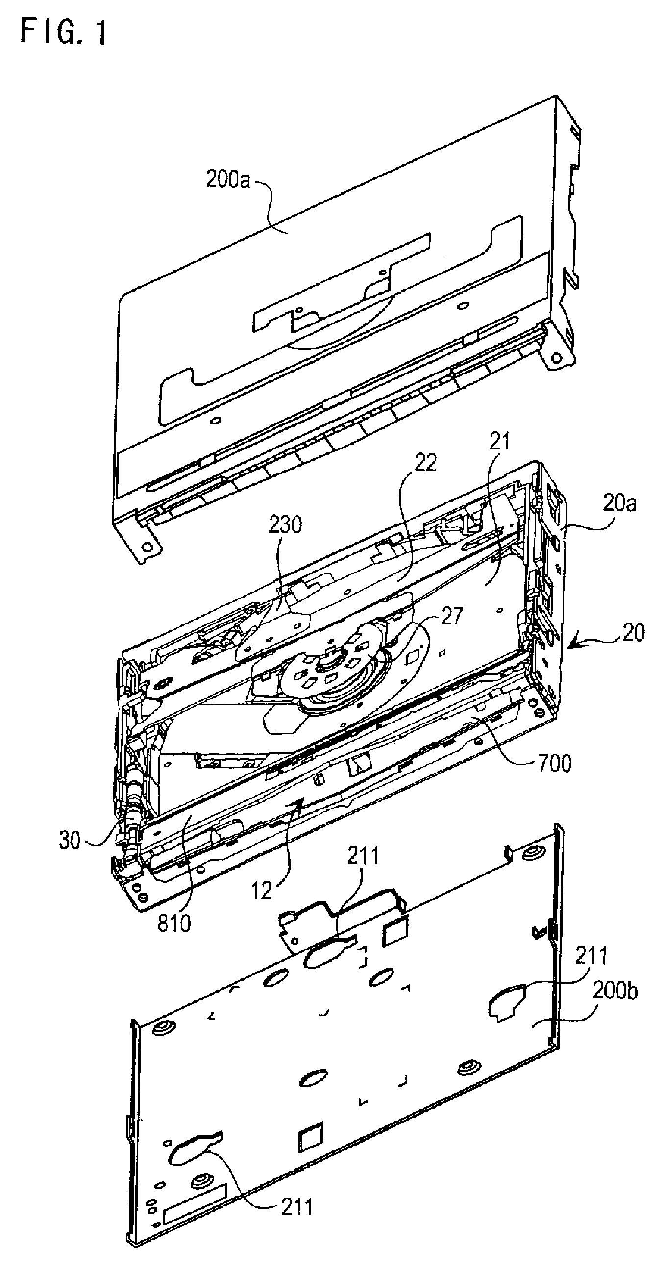
[0069]FIG. 1 is an exploded perspective view showing a construction of a disc player apparatus according to the present invention. The disc player apparatus 10 is a player for a disc 11 (FIG. 9, FIG. 10) such as a DVD (Digital Versatile Disc). However, the disc 11 (recording medium) played by the disc player apparatus 10 is not limited to DVD, and may be other recording media such as a CD (Compact Disc).

[0070]As shown in FIG. 1, the disc player apparatus includes: a main body case 20 which serves as a casing that houses parts provided therein and a disc 11 when it is inserted; as well as an u...


PUM

PropertyMeasurementUnit
outer diameteraaaaaaaaaa
timeaaaaaaaaaa

Abstract

There is provided a disc player apparatus capable of transporting a disc (11) by holding the disc (11) between a lower roller (70) and an upper roller (80). The lower roller (70) and the upper roller (80) are rockably supported with respect to a main body (20a). A flat spring (210) which urges the upper roller (80) is attached to an upper case (200a) that is attached to the main body (20a). The urge of the flat spring (210) is applied via a roller support member (810) which supports the upper roller (80). The pressure is applied evenly to the upper roller (80), enabling to reduce diagonal travel of the disc for example, and to transport the disc smoothly.

Description

TECHNICAL FIELD[0001]The present invention relates to disc player apparatuses which replay from and / or record to discs such as CD (Compact Disc) and DVD (Digital Versatile Disc).BACKGROUND ART[0002]Among disc player apparatuses which replay from and / or record to discs such as CD and DVD are those provided with a slot-in type disc transporting mechanism in which the disc is transported between a disc transporting roller and a disc guide roller by rotating movement of the transporting roller. The slot-in type disc player apparatuses are used popularly in car audio systems, etc.[0003]Slot-in type disc player apparatuses include: a disc replay unit provided with a turntable and an optical pickup; a disc loading mechanism provided with loading rollers for moving the disc in and out of the disc player, a disc clamping mechanism for placing the disc onto the turntable; and so on, assembled in a case.[0004]In these slot-in type disc player apparatuses, when the disc is moved to a predetermi...

Claims


Application Information

Patent Timeline
Patent Type & Authority Patents(United States)
IPC IPC(8): G11B17/04
CPCG11B17/028G11B17/0286G11B17/0404G11B17/051G11B17/04G11B33/08
Inventor AOKI, SHINICHIZENIMOTO, YOICHIMATSUOKA, TORU
Owner SANYO ELECTRIC CO LTD
Why Eureka
Try Eureka