
Multipurpose work site utility carrier

a utility carrier and multi-purpose technology, applied in the field of work site utility carriers, can solve the problems of inability to provide the full functionalities of a hand truck, a retractable work bench and none provide the full functionalities of a hand truck, a safe place to store tools, and a dolly

Inactive Publication Date: 2010-10-19
LOWE ARCHIE
View PDF12 Cites 39 Cited by
  • Summary
  • Abstract
  • Description
  • Claims
  • Application Information

AI Technical Summary

Benefits of technology

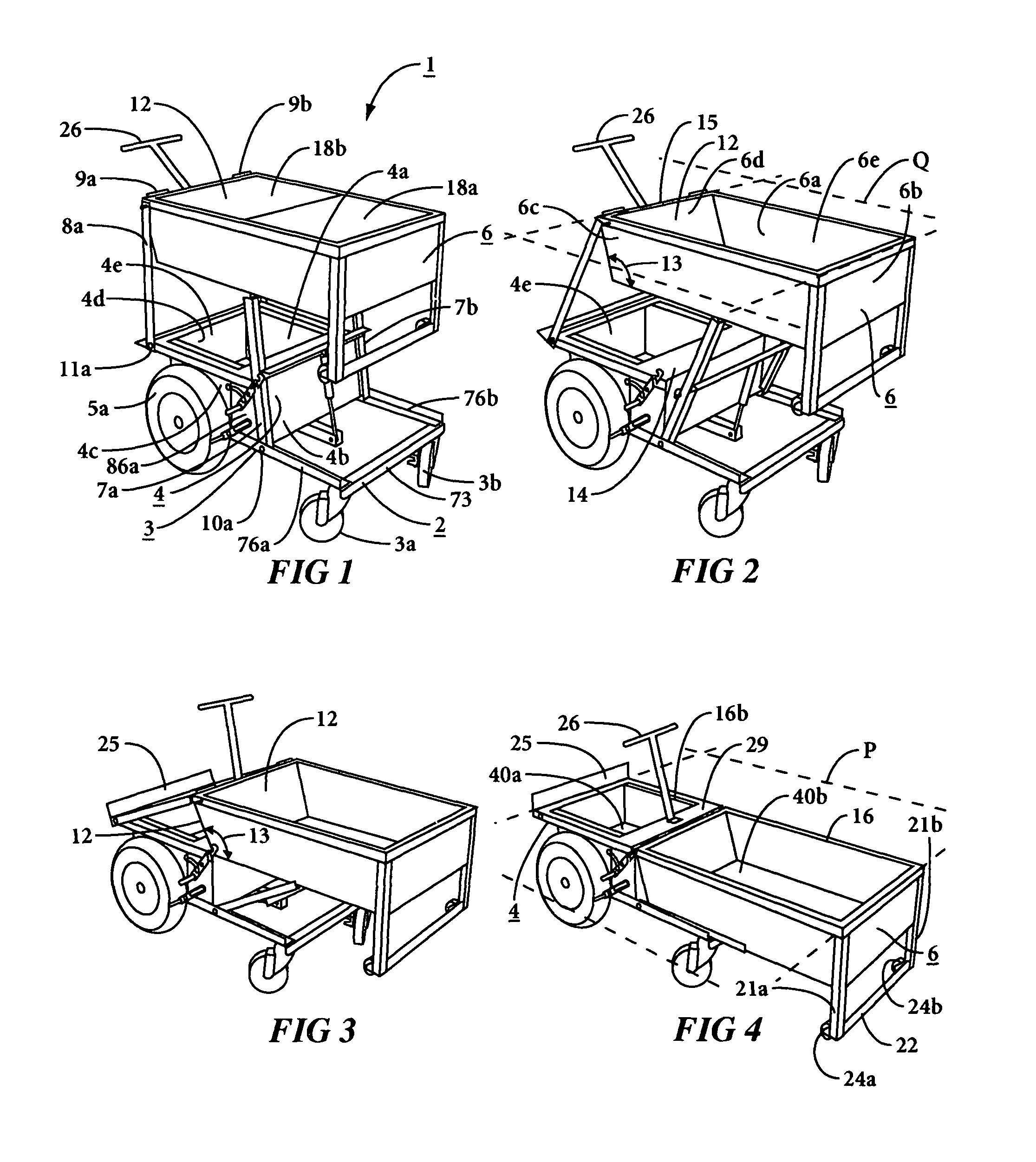
[0009]In accordance with an illustrative embodiment of the invention, a work site utility carrier consists of an elongate chassis. A first structure, box-like in shape and providing a bottom tool box, is formed into a first end of the chassis. A second box-like structure that may be a second or top tool box is pivotally mounted on two rear legs that hinge to the top outer edge of the first structure; and on two front legs that hinge to the chassis. The pivotable mounting allows the second structure and its toolbox to transition between a retracted position and an extended position. In the retracted position the top tool box rests on the chassis base adjacent to the bottom tool box. In the extended position the top structure and its toolbox is stationed above the bottom structure.
[0011]The first structure may be supported on wheels such as two fixed pneumatic rear wheels and two front castors to provide mobility for the carrier in its retracted or extended positions. When all four wheels rest on a floor the carrier is in a dolly mode. A hinged and latchable undercarriage disposed on an end of the top toolbox serves as dolly handle. Advantageously the undercarriage also mounts a pair of mini-wheels that extend below the top toolbox to assist in loading / unloading into and out of a pickup truck. The carrier in dolly mode may be wheeled around a worksite on the pneumatic tires and castors, by unlatching the undercarriage and raising the dolly handle to a comfortable user position.
[0013]An ergonomic handle hinged to an upper edge of the bottom toolbox enables the second structure to be raised and lowered through its pivoting motion. Advantageously, a gas lift spring connected between the chassis and the bottom of the top toolbox compensates for the weight of tools to make movement between the upright and lowered positions. easier for the tradesman.
[0015]Braking devices actuated by a foot lever engage and disengage to the pneumatic wheels. The brakes keep the carrier from rolling in the work bench mode; prevent movement on an incline or when converting from one mode to another; and help keep the carrier in place when transported in a pickup truck.
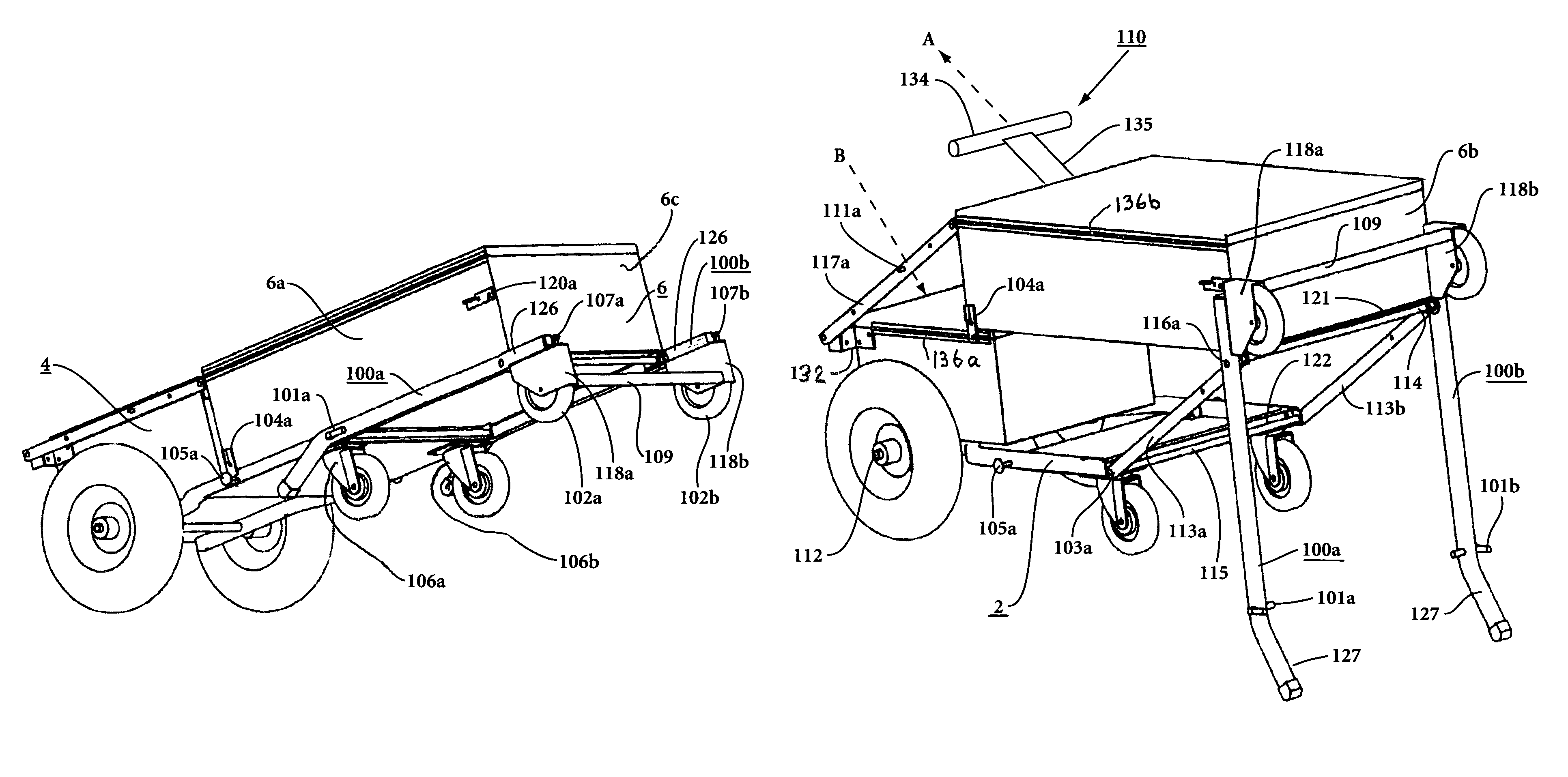
[0016]In accordance with an improvement described in this continuation-in-part application, the pivot points of the front legs are relocated from a central portion of the chassis and a mid-part of the second receptacle, to end portions of the chassis and the second receptacle. In the description of the improvement hereinafter, the pivoting members are “articulating arms”. Two “wheelbarrow” handles are pivotally attached at the lower outer end of the second receptacle at the pivot points of the second articulating arm pair. These handles serve several purposes. The handles' top ends support a third wheel pair connected by a grip. The third wheel pair facilitates maneuvering the carrier onto and off of a pick-up truck bed. In this pivot position the handles are secured to the chassis. In a second pivot position the handles are pivoted 90 degrees into a position essentially perpendicular to a planar bottom surface of the second receptacle and locked in that position. The handles are now a powerful lever allowing the carrier in hand truck mode to be in a more nearly vertical posture during use. This greatly reduces the lifting force needed and also improves carrier maneuvering up and down stairs.
[0017]From this upright hand truck mode, in preparation to transition to the work bench mode, the handles are lowered to the supporting floor. The carrier now is supported on the fixed wheels and the handles' outer ends. In this “semi-inclined” state, the second receptacle is already partially elevated and thus requires less lifting to fully-elevate. Movement to full bench mode is accomplished by pulling lightly on a handle and simultaneously applying foot force to the chassis. With the wheelbarrow handle ends acting as brakes, this movement causes the chassis to begin moving beneath the second receptacle on its fixed wheels. This motion also commences pivoting of the articulating arms. As the fixed wheel pair moves, the force needed to continue chassis movement into position underneath the second receptacle decreases exponentially due to an increasing mechanical advantage as the articulating arms proceed toward the vertical. In full workbench mode the handles are secured to the lower hinge point of one pair of the articulating arms to rigidify the workbench support system and reduce wracking. The lower handle ends continue to serve as brakes. To transition the carrier to a mobile workbench mode, the handles are disengaged from the articulating arm pair and the second receptacle. The handles are again free to pivot. By pulling lightly on the grip, the handles pivot to lower the second set of chassis wheels to the ground. The handles are placed on support pins extendable from the chassis to keep them out of the way during movement of in its mobile work bench mode.

Problems solved by technology

For work such as heavy maintenance, plumbing or carpentry the tools are heavy and numerous.
While the preceding prior art work site utility carriers each offer some versatilities and multiple uses, none provide the full functionalities of a hand truck, a retractable work bench, a safe place to store tools, and a dolly.
Moreover, none provide a mechanism specifically adapted to allow the utility carrier to be loaded readily by a tradesman into and out of the bed of a pick-up truck.

Method used


Image

  • Multipurpose work site utility carrier
  • Multipurpose work site utility carrier
  • Multipurpose work site utility carrier

Examples


Embodiment Construction

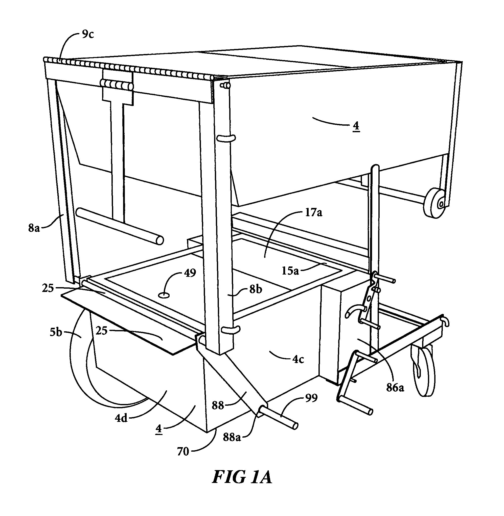
[0050]An illustrative embodiment of utility carrier 1 is shown in FIGS. 1-4. Carrier 1 consists of a chassis 2 formed as an elongate frame of welded or bolted sections of angle irons 76a, 76b joined by transverse L-bracket 73. One or more castor wheels are mounted at one end of chassis 2, the 2-wheel set shown in FIG. 1 denoted 3a, 3b being preferred. Pneumatic tires 5a, 5b are mounted at the other end of chassis 2, both shown in FIG. 15.

[0051]A first structure 4 illustrated as a 4-sided receptacle is affixed to and extends from angle irons 76a, 76b. A second structure 6 illustrated as another 4-sided receptacle is pivotally mounted at one end on structure 4 and at its center portion on chassis 2. It is understood that either structure 4 or structure 6 may take some shape other than a 4-sided box. For purposes of describing the invention, the general term “structure” is used; and the structures 4 and 6 illustrated herein are 4-sided receptacles.

[0052]Structure 6 may be formed as a r...


PUM


Abstract

This disclosure describes a work site utility carrier that configures as a dolly or hand truck in its retracted mode and a work bench in its elevated mode. Pivoting arm pairs enable the carrier's lower and upper receptacles to be transitioned between modes. Two “wheelbarrow” handles are pivotally attached at the lower outer end of the upper receptacle. When oriented at right angles to the upper receptacle bottom, the handles lessen the effort needed to maneuver the carrier. In a “semi-inclined” position the carrier rests in part on the handle outer ends, with much of the mass of the upper receptacle already elevated. Full elevation is facilitated by moving the lower receptacle toward the handle outer ends which act as brakes to keep the carrier stationary during the elevation.

Description

[0001]This application is a continuation-in-part application of earlier non-provisional U.S. application Ser. No. 11 / 097,908, filed on Apr. 4, 2005 now U.S. Pat. No. 7,306,245.TECHNICAL FIELD[0002]This invention relates to work site utility carriers that serve multiple materials handling purposes for craftsman and tradesmen on-the-job. In particular, the invention relates to a unitary self-contained carrier that serves as a hand truck, a dolly, a toolbox and a workbench.BACKGROUND OF THE INVENTION[0003]The work routines of many tradesmen today require that tools and materials be brought to the job and moved around the job location; and that some work be performed on a workbench. For work such as heavy maintenance, plumbing or carpentry the tools are heavy and numerous. Supplies such as plaster buckets, paint cans, pipe fittings and the like add weight and heft to the worker's on-the-job materials. Many tradesmen transport their tools and supplies in a pick-up truck, thus having to l...

Claims


Application Information

Patent Timeline
IPC IPC(8): B62B1/00B62B3/02
CPCB25H1/04B25H1/12B25H3/02B62B3/025B62B5/0003B62B1/002B62B5/0485B62B2206/00
Inventor LOWE, ARCHIE
Owner LOWE ARCHIE
Learn More