Cooling device and projector

a cooling device and projector technology, applied in the direction of electrical apparatus casings/cabinets/drawers, instruments, domestic cooling apparatus, etc., can solve the problems of deteriorating image quality, difficult to ensure that the heat in the sealed structure is appropriately absorbed by the heat transfer member, and deteriorating optical modulator performance, etc., to achieve efficient cooling, efficient cooling, and enhanced heat absorption efficiency

Inactive Publication Date: 2010-10-19
COLUMBIA PEAK VENTURES LLC
View PDF25 Cites 10 Cited by
  • Summary
  • Abstract
  • Description
  • Claims
  • Application Information

AI Technical Summary

Benefits of technology

[0010]An advantage of some aspects of the invention is to provide a cooling device and a projector which have an enhanced heat absorption efficiency.

Problems solved by technology

In the projector, when dust, lamp black or the like is attached on a surface of the optical modulator, image quality of a projected image is deteriorated.
In addition, since the optical modulator such as a liquid crystal panel is generally heat-sensitive, the optical modulator may be deteriorated due to heat caused by irradiation of a light beam from the light source device.
In the arrangement, since a surface area of the heat transfer member disposed in the sealed structure is comparatively small, it is difficult that the heat in the air in the sealed structure is appropriately absorbed by the heat transfer member.
In other words, a heat absorption amount transferred to a heat absorbing surface of the thermoelectric conversion element via the heat transfer member is comparatively small, so that it is difficult to enhance a ratio of a heat absorption amount of heat absorbed from a to-be-cooled object (the air in the sealed structure) to an electric power consumption of the cooling device (the heat absorption efficiency).
In addition, power consumption of the thermoelectric conversion element needs not be unnecessarily increased, thereby contributing to power-saving of the projector.
In such a case, heat is transferred from a large heat-absorption-amount portion of the heat-absorbing-side heat conductive member to a small heat-releasing-amount portion in the heat-releasing-side heat conductive member, so that sufficient heat absorption efficiency can not be ensured in the cooling device.
Hence, the heat-absorbing-side fin members absorb less heat from the air (to-be-cooled object), so that sufficient heat absorption efficiency can not be ensured in the cooling device.
However, such an arrangement may cause following problems.
Hence, when the spacer having a predetermined heat resistance is interposed between the heat-releasing-side heat conductive member and the heat releasing surface, the temperature of the heat releasing surface becomes large, so that it is difficult to maintain the temperature difference between the heat releasing surface and the heat absorbing surface small.
In other words, it is difficult to enhance the heat absorption efficiency.
Accordingly, for example, when the surface area of the heat-absorbing-side heat conductive member is set larger than that of the heat-releasing-side heat conductive member, it is difficult to appropriately release a comparatively large heat releasing amount QD from the heat releasing surface via the heat-releasing-side heat conductive member to the outside air.
In such a case, for example, it is necessary to increase the rotation speed of the cooling fan cooling the heat-releasing-side heat conductive member, which obstructing noise reduction of the projector.
Hence, for example, the rotational speed of the cooling fan that cools the heat-releasing-side heat conductive member needs not be unnecessarily increased, thereby contributing to noise-reduction of the projector.

Method used


Image

  • Cooling device and projector
  • Cooling device and projector
  • Cooling device and projector

Examples


first exemplary embodiment

[0068]A first exemplary embodiment of the invention will be described below with reference to the drawings.

[0069]1 External Arrangement

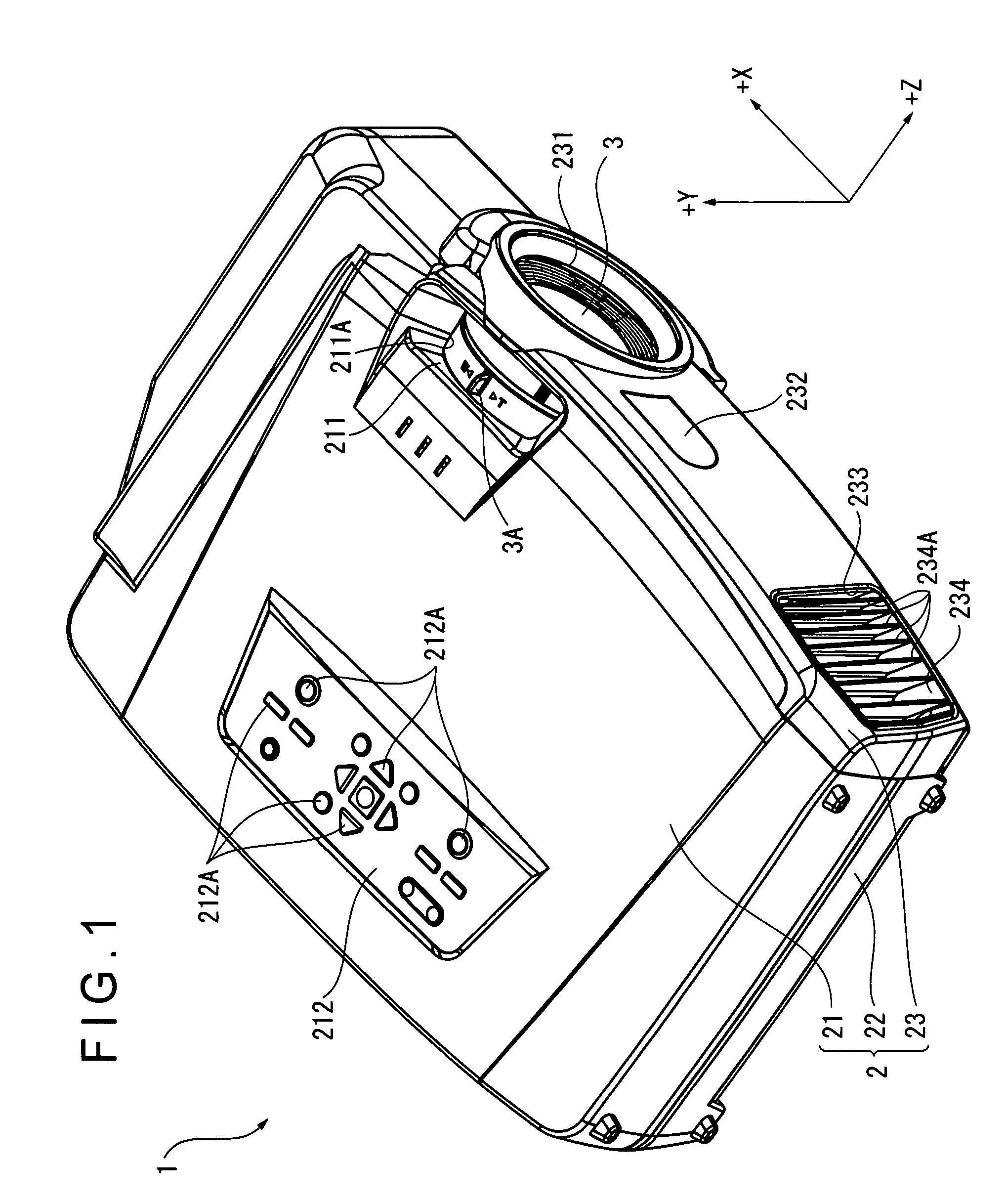
[0070]FIG. 1 is a perspective view showing an external appearance of a projector 1 of the first exemplary embodiment. Specifically, FIG. 1 is a perspective view of the projector 1 when seen from an upper front side. Note that, in FIG. 1, a direction in which an optical image is projected is defined as the Z axis and two axes orthogonal to the Z axis are defined as the X axis (a horizontal axis) and the Y axis (a vertical axis) for easy understanding. In the other figures, the same is applied.

[0071]The projector 1 modulates a light beam irradiated from a light source in accordance with image information to form an optical image and projects the optical image on a screen (not shown) in an enlarged manner. As shown in FIG. 1, the projector 1 includes a substantially rectangular parallelepiped exterior casing 2 and a projection lens 3 as a projection opt...

second exemplary embodiment

[0231]Next, a second exemplary embodiment of the invention will be described with reference to the attached drawings.

[0232]In the description below, the same components as those in the first exemplary embodiment are indicated by the same reference numerals for omitting or simplifying detailed description thereof.

[0233]FIG. 22 shows a structure of a peltier unit 711A of the second exemplary embodiment. Specifically, FIG. 22 is a perspective view of the peltier unit 711A when seen from the plus X axis direction side (the side remote from the projection lens 3).

[0234]The second exemplary embodiment differs from the first exemplary embodiment in a shape of a heat-releasing-side heat conductive member 7116 of the peltier unit 711A as shown in FIG. 22. The other arrangements are the same as those of the first exemplary embodiment.

[0235]As shown in FIG. 22, similarly to the heat-releasing-side heat conductive member 7115, the heat-releasing-side heat conductive member 7116 includes the pla...


PUM


Abstract

A cooling device with a thermoelectric conversion element having a heat absorbing surface and a heat releasing surface includes: a heat-absorbing-side heat conductive member connected with the heat absorbing surface in a heat-conductive manner; a heat-releasing-side heat conductive member connected with the heat releasing surface in a heat-conductive manner; a plurality of heat-absorbing-side fin members that is disposed to the heat-absorbing-side heat conductive member, protrudes in an out-of-plane direction from an end surface remote from the heat absorbing surface and extends in a predetermined direction; and a plurality of heat-releasing-side fin members that is disposed to the heat-releasing-side heat conductive member, protrudes in an out-of-plane direction from an end surface remote from the heat releasing surface and extends in a predetermined direction intersecting with the plurality of heat-absorbing-side fin members in plan view.

Description

[0001]The entire disclosure of Japanese Patent Application No. 2006-166314, filed Jun. 15, 2006, is expressly incorporated by reference herein.BACKGROUND[0002]1. Technical Field[0003]The present invention relates to a cooling device and a projector.[0004]2. Related Art[0005]There has been known a projector that includes a light source device, an optical modulator that modulates a light beam irradiated from the light source device in accordance with image information to form an optical image; and a projection optical device that projects the optical image in an enlarged manner.[0006]In the projector, when dust, lamp black or the like is attached on a surface of the optical modulator, image quality of a projected image is deteriorated. In addition, since the optical modulator such as a liquid crystal panel is generally heat-sensitive, the optical modulator may be deteriorated due to heat caused by irradiation of a light beam from the light source device.[0007]Accordingly, to ensure st...

Claims


Application Information

Patent Timeline
Patent Type & Authority Patents(United States)
IPC IPC(8): G03B21/16F25B21/02
CPCF25B21/02G03B21/16F25B2321/023F25D19/006
Inventor MOMOSE, YASUNAGAYANAGISAWA, YOSHIYUKI
Owner COLUMBIA PEAK VENTURES LLC
Why Eureka
Try Eureka