HVAC staging control

a technology of hvac equipment and staging, which is applied in the direction of lighting and heating apparatus, heating types, instruments, etc., can solve the problems of ineffective or economically used energy that is used to heat or cool these unoccupied rooms, the single thermostat location may not accurately represent the heating or cooling needs of the structure, and the heating and cooling load of individual areas of the structure may not be satisfied

Active Publication Date: 2010-10-26
ADEMCO INC
View PDF83 Cites 21 Cited by
  • Summary
  • Abstract
  • Description
  • Claims
  • Application Information

AI Technical Summary

Problems solved by technology

However, a single thermostat location may not accurately represent the heating or cooling needs throughout the structure.
As a consequence, the heating and cooling loads of individual areas of the structure may not be satisfied and the temperature of these areas will tend to deviate from the desired temperature.
Energy that is used to heat or cool these unoccupied rooms is not used effectively or economically.
However, a system that has only a single thermostat is generally unable to accurately control different locations in the building at different temperatures.
Although it is possible that each of these thermostats could control a separate fluid temperature conditioning device such as a separate furnace or air conditioner for each zone, that approach is generally neither efficient nor economical.
In an HVAC system having both zone control and a multiple stage fluid temperature conditioning device, it can be challenging to determine the proper control strategy for the multiple stage fluid temperature conditioning device.

Method used


Image

  • HVAC staging control
  • HVAC staging control
  • HVAC staging control

Examples


Embodiment Construction

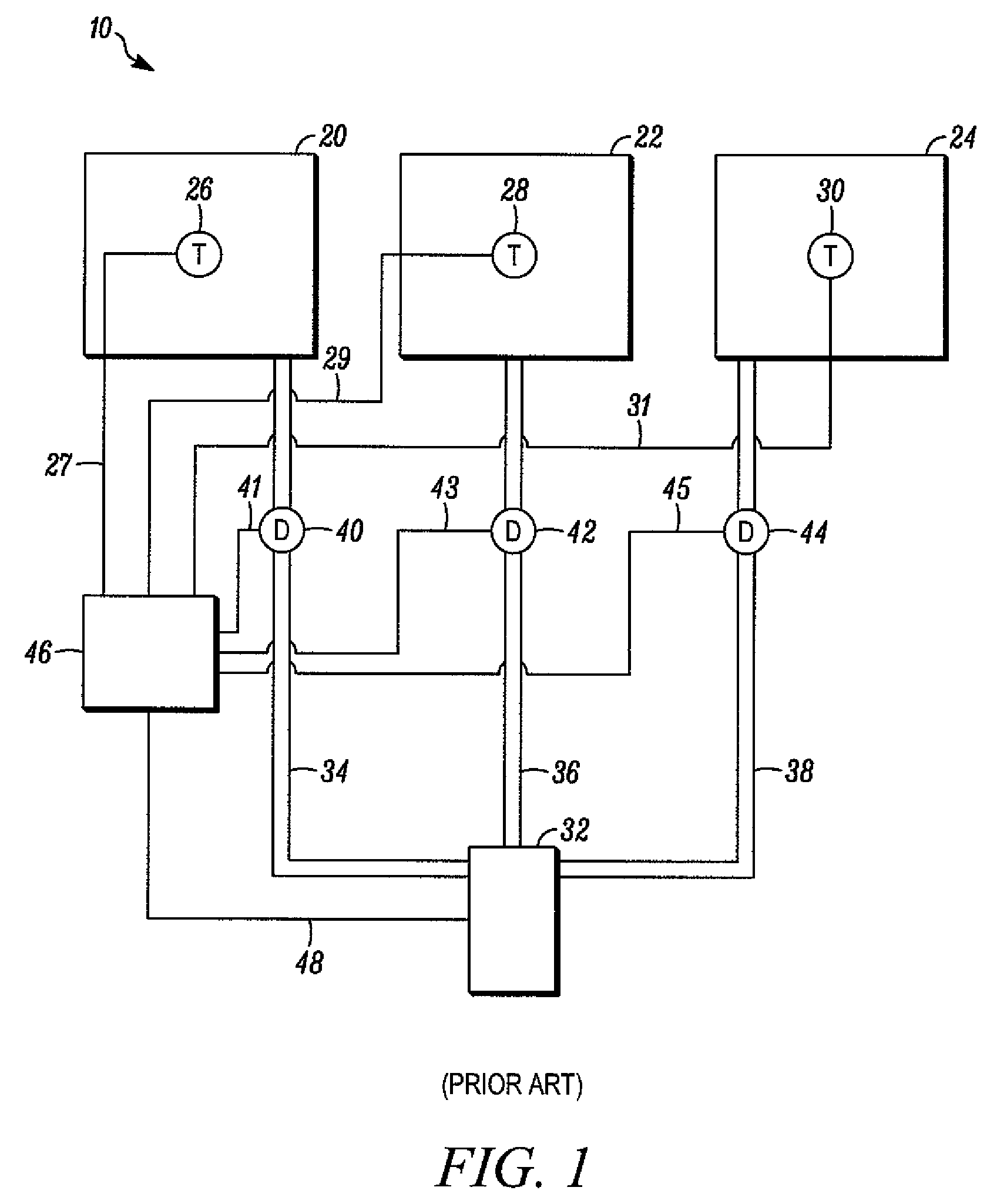
[0021]As discussed above, it may be desirable for a building to have an HVAC system with zone control. FIG. 1 is a schematic of a typical HVAC system 10 having multiple zones. The embodiment of FIG. 1 is shown as having three zones. However, other embodiments having fewer or greater numbers of zones are usable. For example, some systems may have only two zones, while other systems may have four or more zones. Zones 20, 22, 24 are separate areas of a building. Each zone 20, 22, 24 includes a thermostat 26, 28, 30, respectively. A fluid temperature conditioning device 32, also called a conditioning device 32, is provided for increasing or decreasing the temperature of a fluid. For example, conditioning device 32 may be a furnace that increases the temperature of air. In the case where conditioning device 32 is a furnace, heated air is transmitted through ducts 34, 36, 38 to each of zones 20, 22, 24, respectively. Each duct 34, 36, 38 includes a damper 40, 42, 44, respectively, for con...


PUM


Abstract

A controller for an HVAC system having a plurality of zones and having a multiple stage fluid temperature conditioning device. The controller is configured to receive a plurality of thermostat signals and to transmit a signal to control one of a plurality of flow control devices in response to a call for conditioning in one of the plurality of zones. The controller also includes one or more timers that are connected to the thermostat terminals, where the one or more timers are configured to initiate a separate timing count upon each call for conditioning in any one of the plurality of zones. In addition, the controller includes one or more staging terminals for transmitting staging signals to control a multiple stage fluid temperature conditioning device, where the transmission of the staging signals determines whether the conditioning device will operate at a relatively higher output stage. The controller is also configured to make a timing count determination to determine if any one of the separate timing counts initiated upon each call for conditioning in any one of the plurality of zones exceeds a timing delay parameter. The transmission of staging signals depends on the timing count determination. A method is also disclosed.

Description

FIELD OF THE INVENTION[0001]The invention relates to the control of HVAC equipment, and more particularly, to the control of multi-stage HVAC equipment in a system having a plurality of zones.BACKGROUND OF THE INVENTION[0002]Many buildings, particularly relatively small buildings such as single-family houses, have a single heating, ventilation, and air conditioning (HVAC) unit that is controlled by a single thermostat. The HVAC unit typically comprises some type of fluid temperature conditioning device, such as a furnace for heating air, a boiler for heating a liquid or steam, or an air conditioner having an evaporating coil for cooling air. If the fluid is air, it is typically ducted to various locations within the building, or if it is liquid or steam, it is typically piped to heat exchangers at various locations in the building. The thermostat in this type of space conditioning system is typically positioned at a location where the heating and cooling loads are representative of ...

Claims


Application Information

Patent Timeline
Patent Type & Authority Patents(United States)
IPC IPC(8): F24D19/10F24F11/00G05D23/275
CPCF24F11/0012F24F11/006F24F11/30F24F2110/10F24F11/62F24F11/61F24F11/76F24F11/64
Inventor ARNESON, DAVID J.
Owner ADEMCO INC
Why Eureka
Try Eureka