Printhead IC with multi-stage print data loading and firing
What is AI technical title?
AI technical title is built by Patsnap AI team. It summarizes the technical point description of the patent document.
a printhead and data technology, applied in the field of inkjet printers, can solve the problems of increasing the power increasing the size of the drive fet, and reducing the density of the printhead nozzle, so as to prevent nozzle burnout and reduce the duration of the drive puls
Active Publication Date: 2010-10-26
SILVERBROOK RES PTY LTD +1
View PDF12 Cites 8 Cited by
Summary
Abstract
Description
Claims
Application Information
AI Technical Summary
This helps you quickly interpret patents by identifying the three key elements:
Problems solved by technology
Method used
Benefits of technology
Benefits of technology
The present invention provides a printhead IC with an array of nozzles and a drive circuitry for receiving print data and activating the actuators with drive signals in accordance with the print data. The drive circuitry includes a shift register for each nozzle, but instead of a separate shift register for each nozzle, the drive circuitry has enough dot data shift registers for a portion of the nozzle array to allow for a fire command at the end of each portion of the array. This allows for a larger drive FET, which can generate a drive pulse at higher power levels for more efficient drop ejection. The printhead IC also includes open actuator test circuitry for selectively disabling the actuators and temperature sensors for adjusting the drive pulses accordingly. The technical effects of this invention include improved printing efficiency, reduced nozzle failure, and improved reliability of the printhead IC.
Problems solved by technology
This allows much higher print speeds but is more complicated in terms of controlling the operation of a much larger array of nozzles.
However, increasing the power of the drive FET increases its size.
This enlarges the wafer area occupied by the nozzle and its associated circuitry and therefore reduces the nozzle density of the printhead.
Reducing the nozzle density is detrimental to print quality and compact printhead design.
Method used
Image
Click on the blue label to locate the original text in one second.
Reading with bidirectional positioning of images and text.
Examples
Embodiment Construction
[0149]The Applicant has developed a range of printhead devices that use a series of printhead integrated circuits (ICs) that link together to form a pagewidth printhead. In this way, the printhead IC's can be assembled into printheads used in applications ranging from wide format printing to cameras and cellphones with inbuilt printers. One of the more recent printhead IC's developed by the Applicant is referred to internally as wide range of printing applications. The Applicant refers to these printhead IC's as ‘Udon’ and the various aspects of the invention will be described with particular reference to these printhead IC's. However, it will be appreciated that this is purely for the purposes of illustration and in no way limiting to the scope and application of the invention.
Overview
[0150]The Udon printhead IC is designed to work with other Udon ICs to make a linking printhead. The Applicant has developed a range of linking printheads in which a series of the printhead IC's are m...
PUM
Abstract
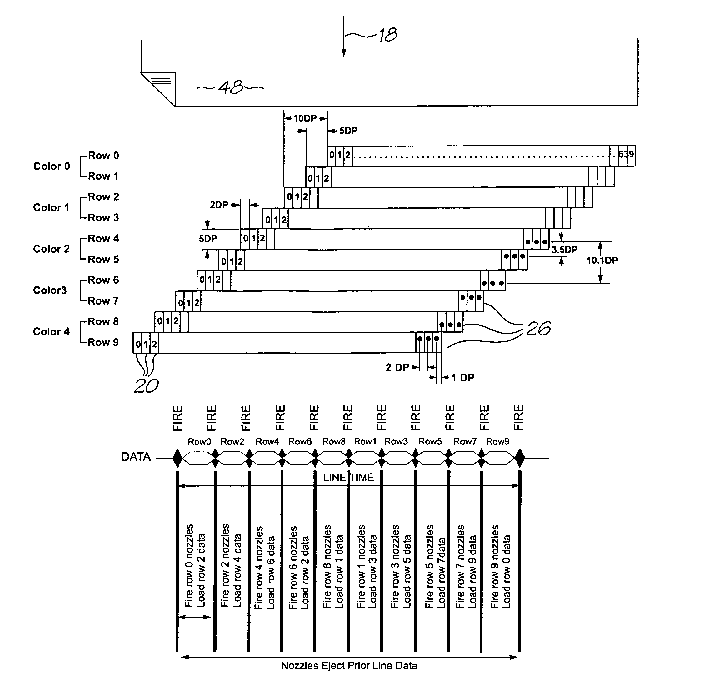
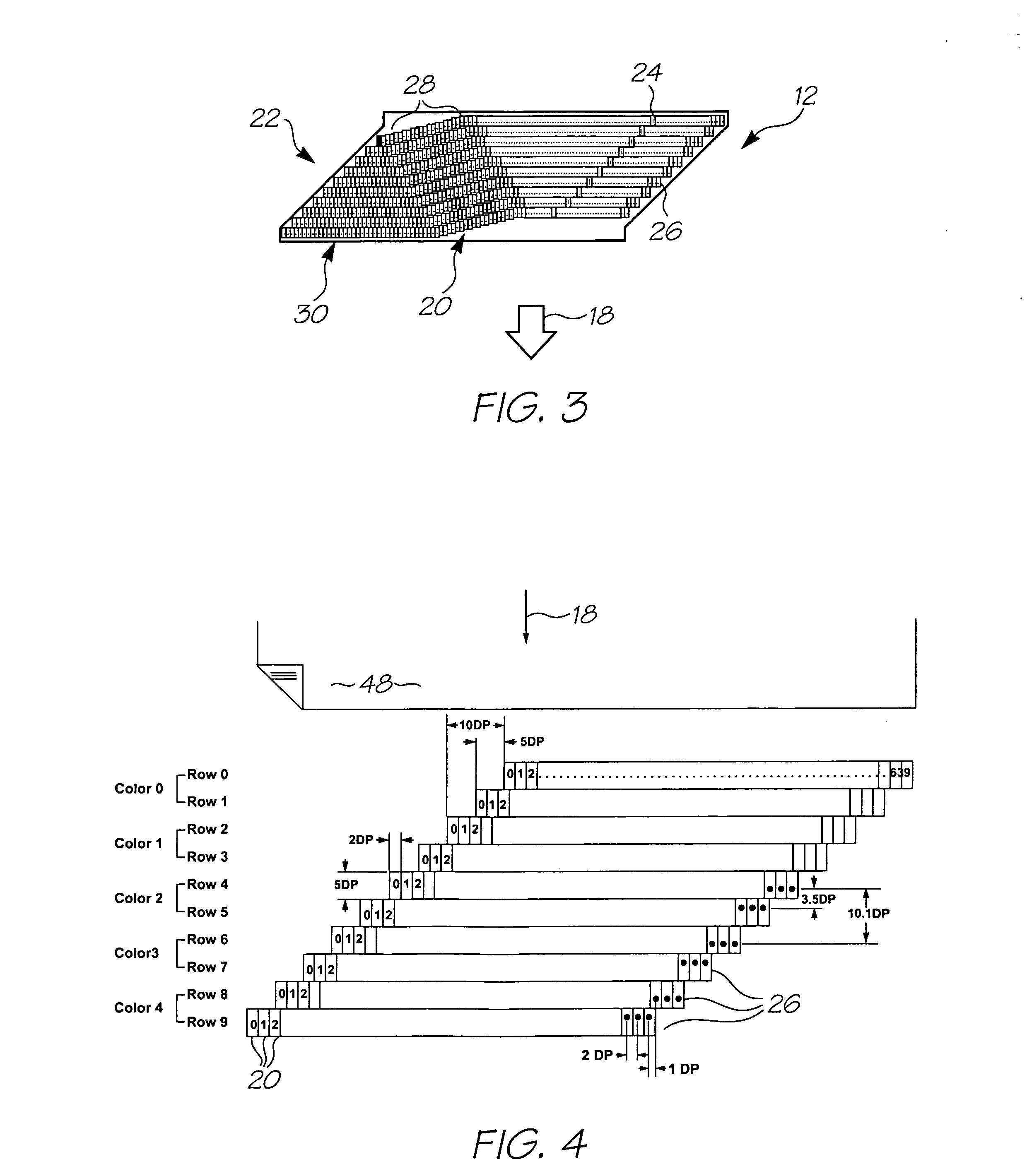
A printhead IC comprising: an array of nozzles; drive circuitry for receiving print data and fire commands from a print engine controller; wherein during use, the drive circuitry receives the print data for the array in a plurality of sequential portions with a fire command at the end of each portion.
Description
FIELD OF THE INVENTION[0001]The present invention relates to the field of inkjet printers. In particular, the invention relates to inkjet printers that have printheads with a number of separate printhead integrated circuits (IC's) defining the nozzles that eject the ink or other printing fluid.[0002]The following applications have been filed by the Applicant simultaneously with the present application:[0003]11 / 544,77811 / 544,77911 / 544,76411 / 544,77211 / 544,77311 / 544,77411 / 544,7757,425,04811 / 544,76611 / 544,7677,384,12811 / 544,77011 / 544,76911 / 544,7777,425,0477,413,288[0004]The disclosures of these co-pending applications are incorporated herein by reference.CROSS REFERENCES TO RELATED APPLICATIONS[0005]Various methods, systems and apparatus relating to the present invention are disclosed in the following US patents / patent applications filed by the applicant or assignee of the present invention:[0006]6,750,9016,476,8636,788,3367,249,1086,566,8586,331,9466,246,9706,442,5257,346,58609 / 505,951...
Claims
Application Information
Patent Timeline
Application Date:The date an application was filed.
Publication Date:The date a patent or application was officially published.
First Publication Date:The earliest publication date of a patent with the same application number.
Issue Date:Publication date of the patent grant document.
PCT Entry Date:The Entry date of PCT National Phase.
Estimated Expiry Date:The statutory expiry date of a patent right according to the Patent Law, and it is the longest term of protection that the patent right can achieve without the termination of the patent right due to other reasons(Term extension factor has been taken into account ).
Invalid Date:Actual expiry date is based on effective date or publication date of legal transaction data of invalid patent.
InventorSHEAHAN, JOHN ROBERTPULVER, MARK JACKSONMORAHAN, BRIAN CHRISTOPHERMOINI, ALIREZAGILLESPIE, TIMOTHY PETERWEBB, MICHAEL JOHNGANNON, MARCELLE LOUISASILVERBROOK, KIA

