Print method, print apparatus, and recording medium driving apparatus

a printing method and printing technology, applied in the direction of digitally marking record carriers, visual presentation using printers, instruments, etc., can solve problems such as the reduction of print quality, and achieve the effect of preventing distortion of visible information printed

Inactive Publication Date: 2010-10-26
SONY CORP
View PDF14 Cites 3 Cited by
  • Summary
  • Abstract
  • Description
  • Claims
  • Application Information

AI Technical Summary

Benefits of technology

[0016]For a print apparatus that prints visible information on a print surface of a rotating printed object by ejecting ink droplets onto the printed object from ejection nozzles provided on a print head, the rotation of the printed object causes displacement in the impact positions of the ink droplets and distortion in the printed visible information, thereby leading to a reduction in print quality.
[0017]It is desirable to provide a print method, a print apparatus, and a recording medium driving apparatus that can prevent distortion occurring for printed visible information when visible information is printed by ejecting ink droplets onto a rotating printed object and can therefore print with high quality.
[0021]The print method, print apparatus, and recording medium driving apparatus according to the embodiments of the present invention can carry out printing that compensates for displacements in the impact positions of ink droplets and can thereby prevent distortion in the visible information printed on the printed object.

Problems solved by technology

For a print apparatus that prints visible information on a print surface of a rotating printed object by ejecting ink droplets onto the printed object from ejection nozzles provided on a print head, the rotation of the printed object causes displacement in the impact positions of the ink droplets and distortion in the printed visible information, thereby leading to a reduction in print quality.

Method used


Image

  • Print method, print apparatus, and recording medium driving apparatus
  • Print method, print apparatus, and recording medium driving apparatus
  • Print method, print apparatus, and recording medium driving apparatus

Examples


first embodiment

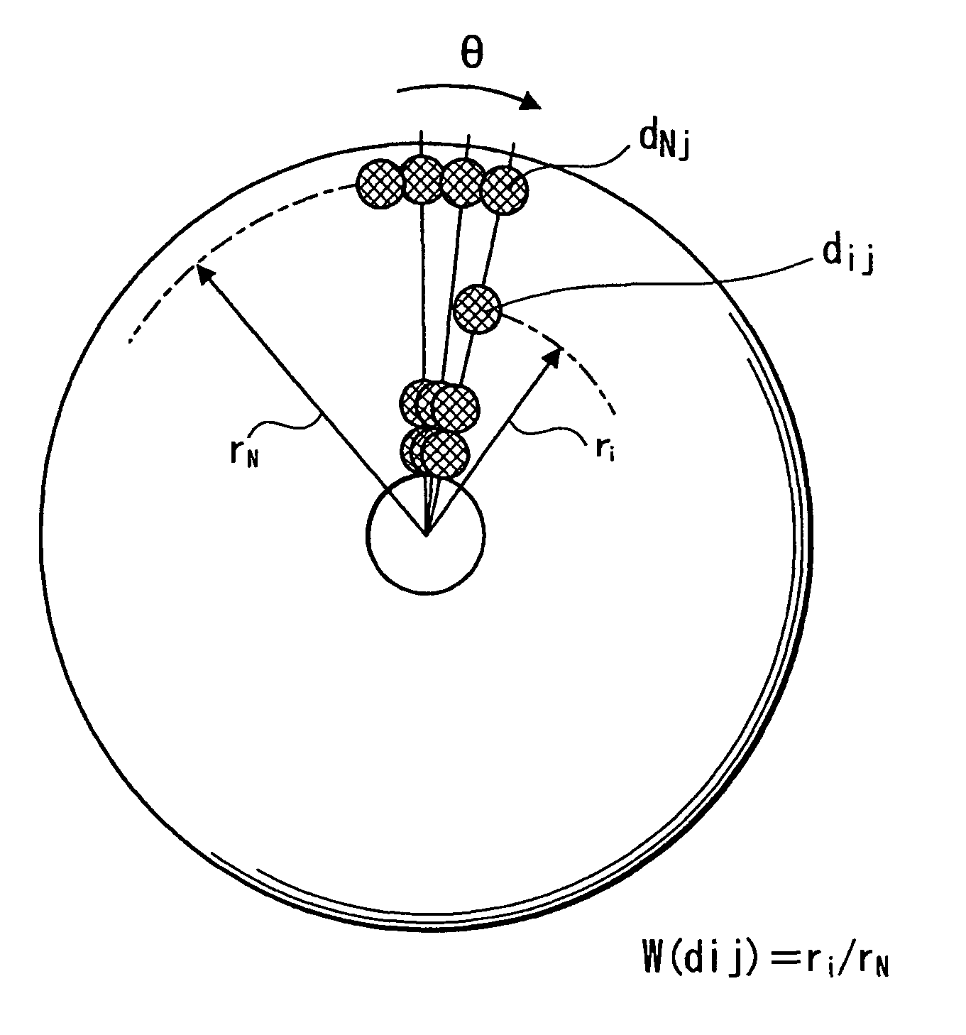
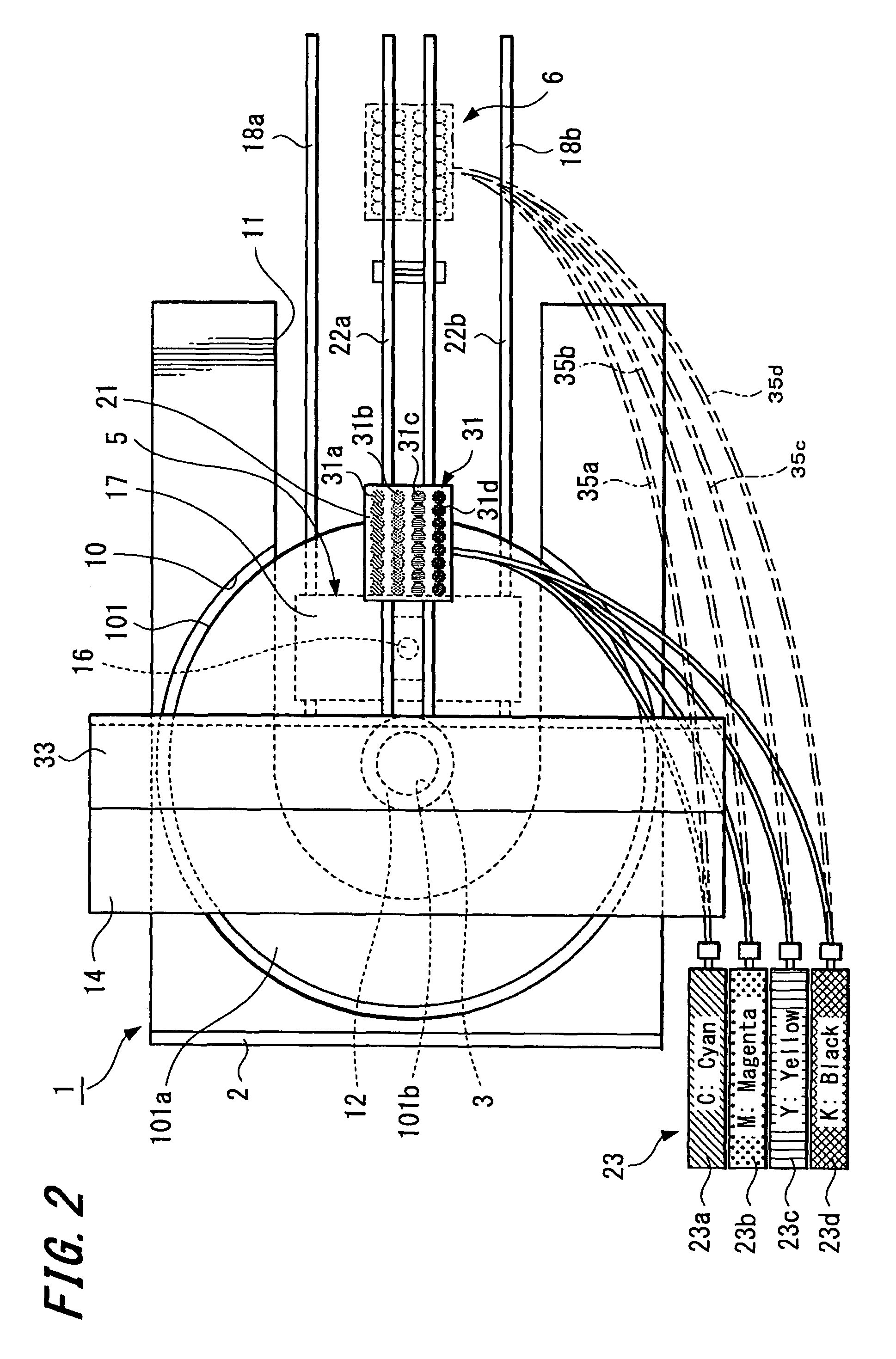
[0035]FIGS. 2 to 11B are diagrams for explaining embodiments of the present invention. FIGS. 2 to 9 show a print apparatus and a print method according to the present invention. FIG. 2 is a plan view. FIG. 3 is a front view. FIG. 4 is a block diagram showing the flow of signals. FIG. 5 is a flowchart showing the flow of operations in a control unit. FIGS. 6A to 6C are diagrams for explaining a conversion from biaxial perpendicular coordinate data to polar coordinate data. FIGS. 7A and 7B are diagrams for explaining impact position correction that corrects displacements in the impact positions of ink droplets. FIG. 8 is a diagram for explaining correction weightings for dot density correction. FIGS. 9A to 9F are diagrams for explaining a process as far as generation of ink ejection data from impact position-corrected polar coordinate data.

second embodiment

[0036]FIGS. 10A, 10B and 11A, 11B are diagrams for explaining a print method according to the present invention. FIG. 10A is a diagram for explaining a print head. FIG. 10B is a diagram for explaining the ejection timings of ink droplets. FIG. 11A is a diagram for explaining the impact positions of ink droplets ejected at the same timing. FIG. 11B is a diagram for explaining the impact positions of ink droplets ejected at different timings.

[0037]FIGS. 2 and 3 show an optical disc apparatus 1 (recording medium driving apparatus) that is a first embodiment of a print apparatus according to the present invention. The optical disc apparatus 1 is capable of recording (writing) a new information signal onto and / or reproducing (reading) an information signal that has been recorded in advance from an information recording surface (or simply “recording surface”) of an optical disc 101, such as a CD-R or DVD-RW, as a specific example of a “printed object”. The optical disc apparatus 1 is also...


PUM


Abstract

A print method that prints visible information by ejecting ink droplets from a print head onto a printed object rotated by a rotational driving unit is provided. The print method includes the steps of: carrying out impact position correction that corrects displacements in impact positions of the ink droplets to convert the visible information to impact position-corrected polar coordinate data when converting the visible information from biaxial perpendicular coordinate data to polar coordinate data; generating ink ejection data based on the impact position-corrected polar coordinate data; and printing the visible information by ejecting the ink droplets onto the printed object based on the ink ejection data.

Description

CROSS REFERENCES TO RELATED APPLICATIONS[0001]The present invention contains subject matter related to Japanese Patent Application JP 2006-326264 filed in the Japanese Patent Office on Dec. 1, 2006, the entire contents of which being incorporated herein by reference.BACKGROUND OF THE INVENTION[0002]1. Field of the Invention[0003]The present invention relates to a print method that rotates a disc-shaped recording medium, such as a CD-R (Compact Disc-Recordable) or a DVD-RW (Digital Versatile Disc-Rewritable), a semiconductor storage medium, or other printed object and prints visible information such as characters and designs by ejecting ink droplets onto a label surface or other print surface of the rotating printed object, and also relates to a print apparatus and recording medium driving apparatus that use such print method.[0004]2. Description of the Related Art[0005]Japanese Unexamined Patent Application Publication No. 09-265760 (JP 09-265760 A) discloses an example of a print a...

Claims


Application Information

Patent Timeline
Patent Type & Authority Patents(United States)
IPC IPC(8): B41J2/205
CPCB41J2/175B41J3/4071B41J29/38B41M1/40B41J2/01G11B23/38B41M3/00
Inventor ITO, TATSUMIMATSUI, TAKESHIIKEMOTO, YUICHIRO
Owner SONY CORP
Why Eureka
Try Eureka