Purification of carbon dioxide

a carbon dioxide and purification technology, applied in the direction of rectification and condensation, energy input, liquefaction, etc., can solve the problems of reducing the heating and economic value of gas, oxygen presence, and no details regarding how the general idea might be implemented

Active Publication Date: 2010-10-26
AIR PROD & CHEM INC
View PDF29 Cites 83 Cited by
  • Summary
  • Abstract
  • Description
  • Claims
  • Application Information

AI Technical Summary

Benefits of technology

[0239]Advantages of preferred embodiments of the present invention include:

Problems solved by technology

The presence of oxygen may present problems when the carbon dioxide is intended for use in enhanced oil or gas recovery operations due to the possibility of oxidation causing corrosion problems in downhole equipment.
However, no details regarding how the general idea might be implemented were disclosed.
The presence of the carbon dioxide in the stream decreases the heating and economic value of the gas.

Method used


Image

  • Purification of carbon dioxide
  • Purification of carbon dioxide
  • Purification of carbon dioxide

Examples


example 1

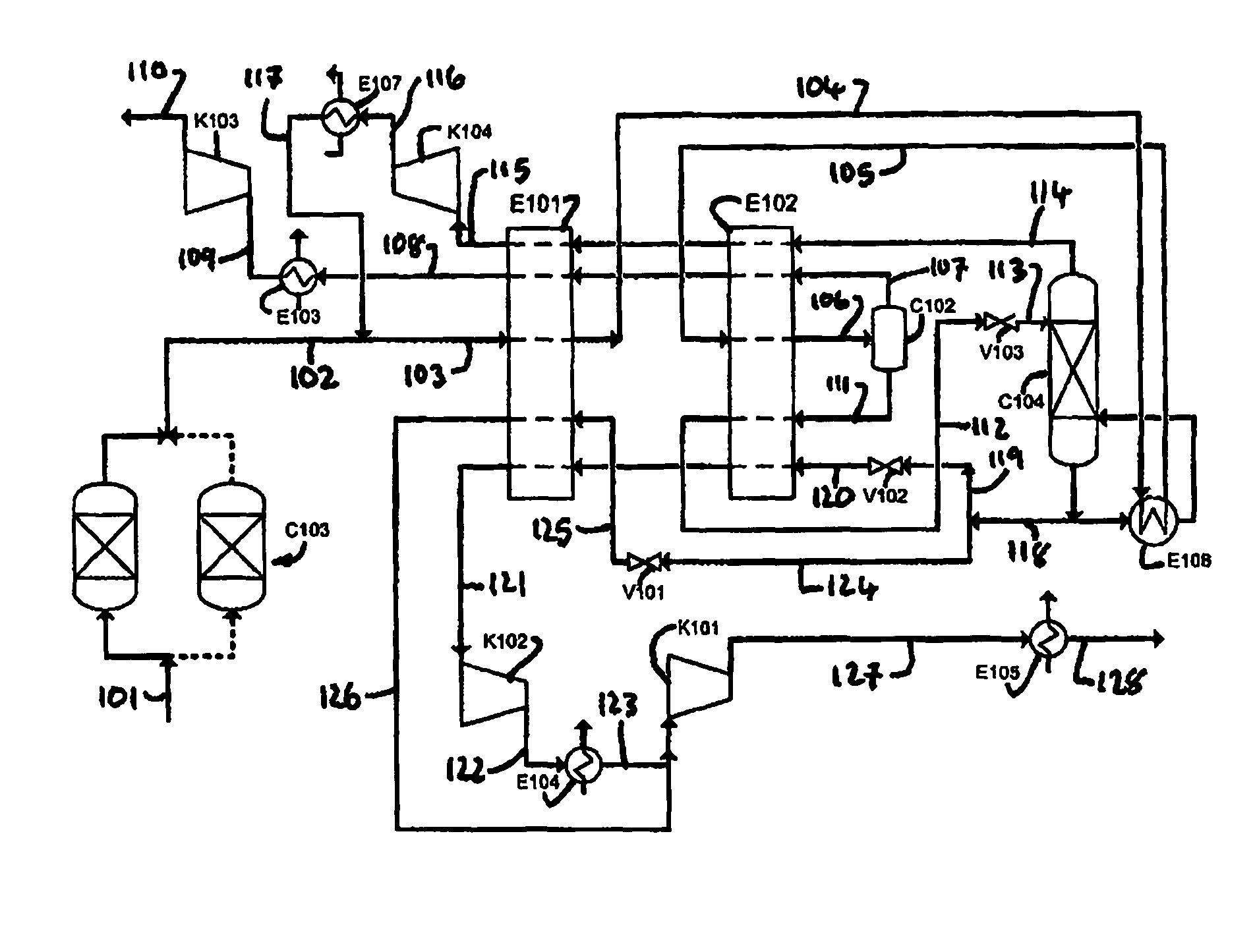
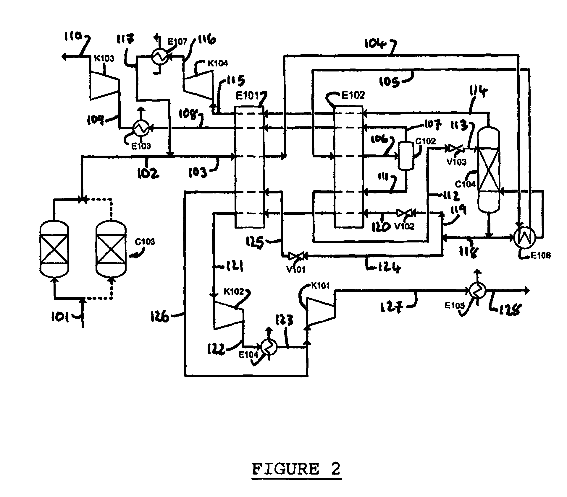
[0232]A computer simulation has been carried out using commercially available simulation software (Aspen Plus Version 2004.1) in which the process depicted in FIG. 2 is integrated with an oxyfuel combustion process in a power generation plant. A heat and mass balance table for the simulation is provided in Table 2.

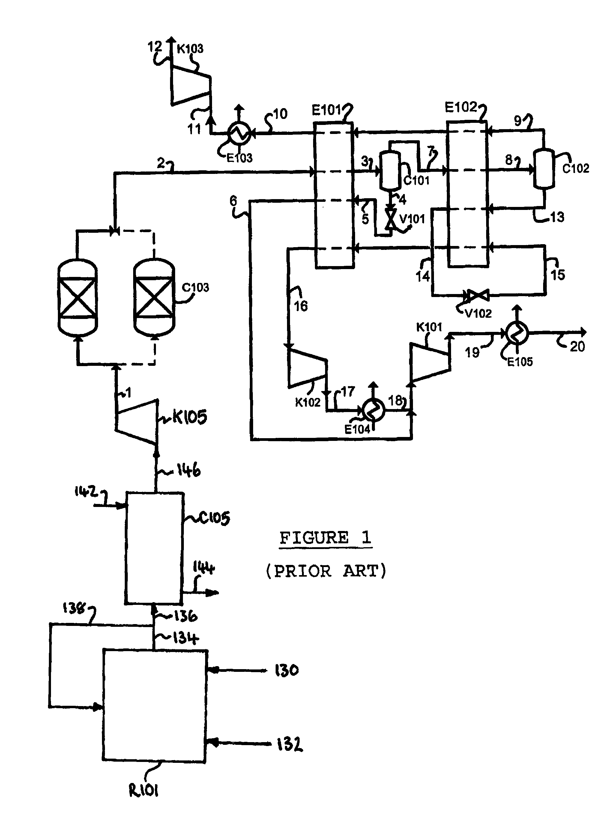
[0233]The simulation achieved the required level of carbon dioxide purity of over 97 mol % (actually about 99.9 mol %), with about 87.4% carbon dioxide recovery. However, the specific power consumption is increased by 3% and carbon dioxide recovery reduced by 1.6% compared to the prior art process shown in FIG. 1.

[0234]A computer simulation (Aspen Plus Version 2004.1) of the same process but vaporizing a third level of liquid carbon dioxide to provide further refrigeration (FIG. 3) indicates that overall power consumption can be reduced by about 13% compared to the process depicted in FIG. 1.

[0235]

TABLE 2Stream Number101102103104105106107108109110Temperature° C.24.8324.832...

example 2

[0236]A computer simulation (Aspen Plus Version 2004.1) has been carried out in which the process depicted in FIG. 2 is integrated with a hydrogen PSA system (not shown). The off gas from the PSA system is compressed to 30 bar to form a stream 101 of compressed off gas which is fed to the process. A heat and mass balance table for the simulation is provided in Table 3.

[0237]The simulation indicates that the carbon monoxide level can be reduced to about 100 ppm.

[0238]

TABLE 3Stream Number101102103104105106107108109110Temperature° C.20.0020.0020.30−3.21−16.35−53.65−53.658.40300.0065.90Pressurebar a3030.00303030303030301.1Flowkg / s54.5954.5659.0559.0559.0559.059.789.789.789.78CompositionCO2mol %71.601671.679972.476872.476872.476872.476823.748423.748423.748423.7484N2mol %0.99510.99621.01831.01831.01831.01832.68592.68592.68592.6859Armol %0.16820.16840.18360.18360.18360.18360.43880.43880.43880.4388H2mol %21.860921.884820.835520.835520.835520.835559.030359.030359.030359.0303H2Omol %0.10920.0...


PUM

PropertyMeasurementUnit
mol %aaaaaaaaaa
mol %aaaaaaaaaa
pressureaaaaaaaaaa

Abstract

A first contaminant selected from oxygen and carbon monoxide is removed from impure liquid carbon dioxide using a mass transfer separation column system which is reboiled by indirect heat exchange against crude carbon dioxide fluid, the impure liquid carbon dioxide having a greater concentration of carbon dioxide than the crude carbon dioxide fluid. The invention has particular application in the recovery of carbon dioxide from flue gas generated in an oxyfuel combustion process or waste gas from a hydrogen PSA process. Advantages include reducing the level of the first contaminant to not more than 1000 ppm.

Description

BACKGROUND OF THE INVENTION[0001]The present invention relates to a process and apparatus for purification of impure liquid carbon dioxide (“CO2”) comprising a first contaminant selected from the group consisting of oxygen (“O2”) and carbon monoxide (“CO”). The process and apparatus have particular application in the recovery of carbon dioxide from waste carbon dioxide gas, for example flue gas from an oxyfuel combustion process or waste gas from a hydrogen (“H2”) pressure swing absorption (“PSA”) process.[0002]There is an urgent need to develop new processes for production of electrical energy from fossil fuels, carbonaceous fuels or hydrocarbon fuels with capture of carbon dioxide. The new processes should ideally be more efficient and cost effective than existing processes. Oxyfuel combustion processes are being considered in this context.[0003]In oxyfuel combustion, a fuel is combusted in pure oxygen with optional recycle of cooled flue gas or steam or water to moderate the flam...

Claims


Application Information

Patent Timeline
Patent Type & Authority Patents(United States)
IPC IPC(8): B01D53/14C01B32/50
CPCC01B31/20F25J3/0252F25J3/0266F25J3/0223Y02C10/12F25J2200/02F25J2200/70F25J2200/76F25J2205/04F25J2210/04F25J2210/70F25J2220/82F25J2230/06F25J2230/32F25J2230/80F25J2240/90F25J2245/02F25J2270/02Y02C10/06Y02P20/129C01B32/50Y02C20/40Y02P20/151B01D53/00F25J3/08
Inventor WHITE, VINCENTALLAM, RODNEY JOHN
Owner AIR PROD & CHEM INC
Why Eureka
Try Eureka