
Thin-film magnetic head in which perpendicular magnetic record head overlaps on reproducing head

a perpendicular magnetic record head and magnetic head technology, applied in the field of thin film magnetic head, can solve the problems of large leakage magnetic field magnitude, inability to solve erasure, and difficulty in degrading or destroying the reproducing element,

Inactive Publication Date: 2010-10-26
TDK CORPARATION
View PDF12 Cites 2 Cited by
  • Summary
  • Abstract
  • Description
  • Claims
  • Application Information

AI Technical Summary

Benefits of technology

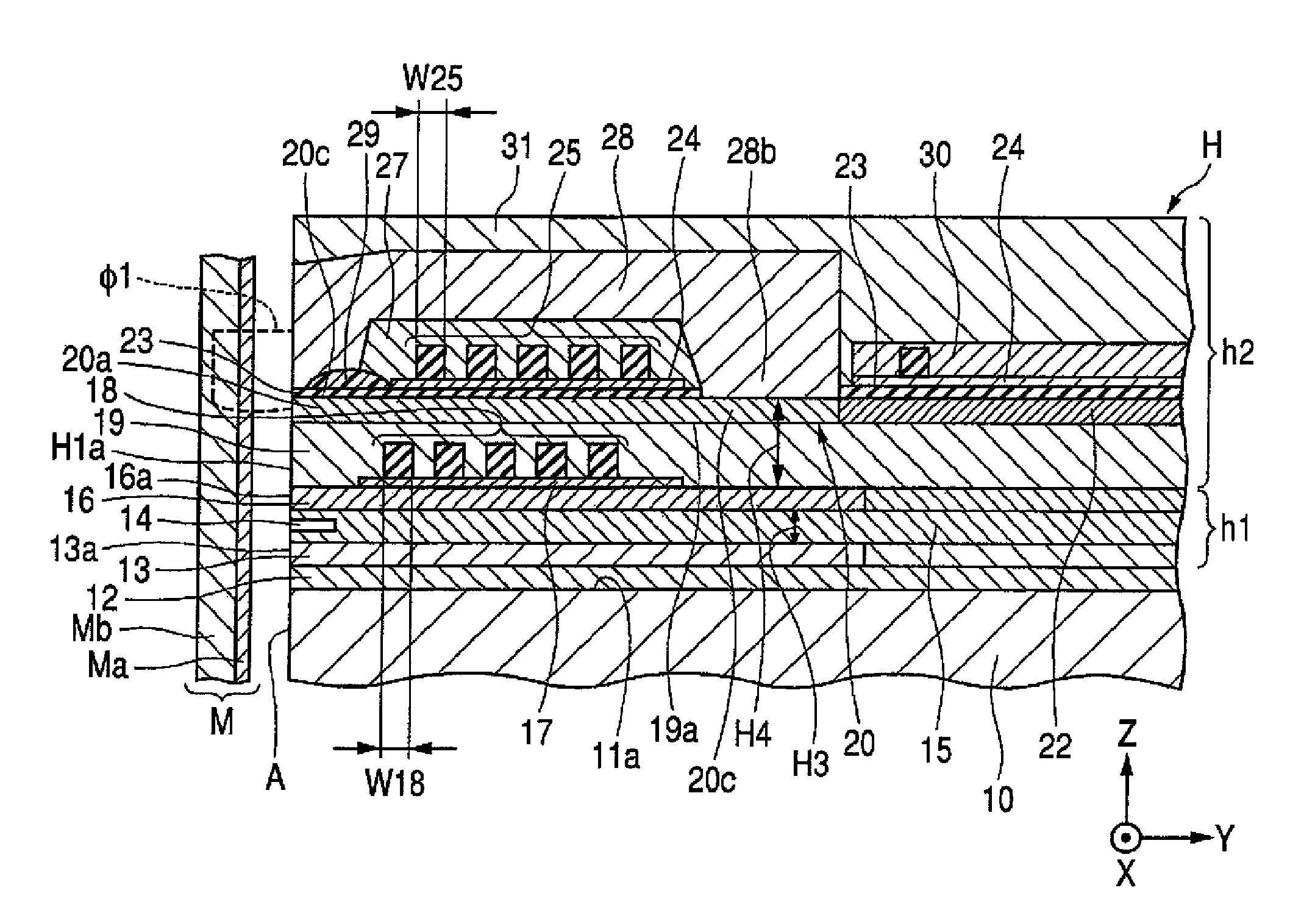
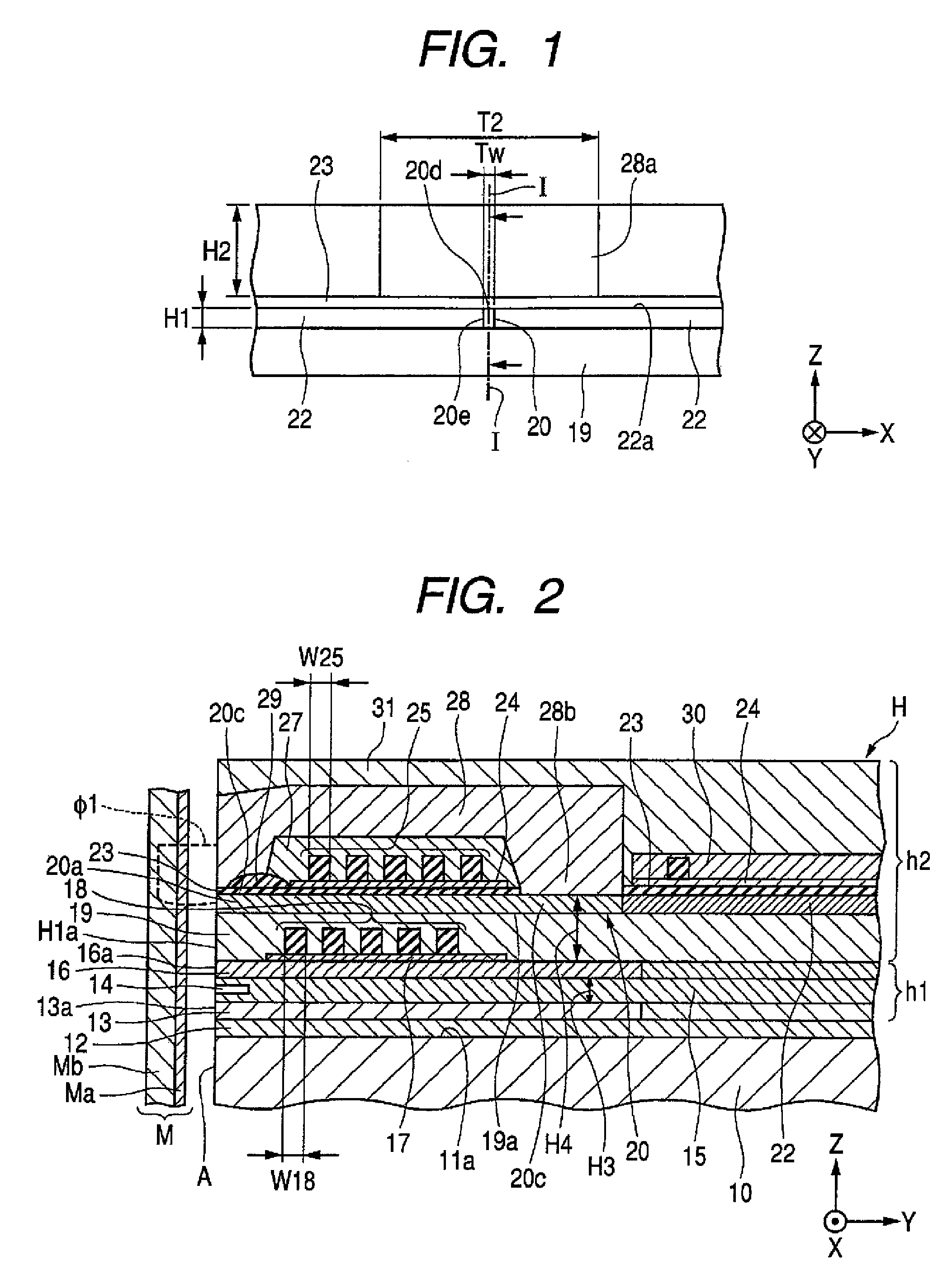
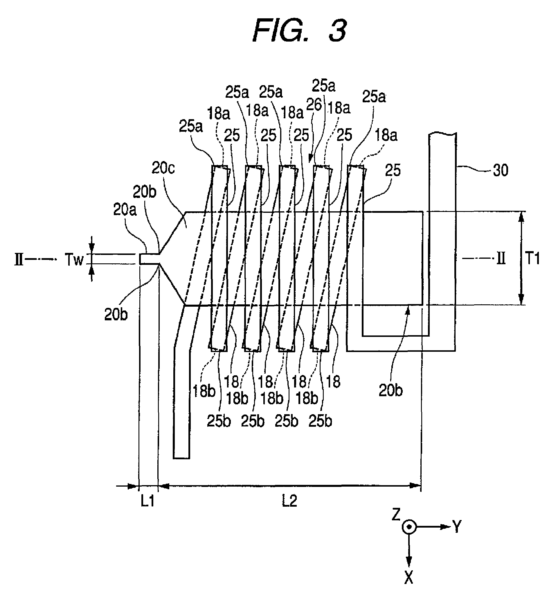
[0011]The present embodiments may obviate one or more of the drawbacks and limitations of the related. For example, in one embodiment, by adjusting a length difference of the height direction of the return-yoke layer, the upper shield layer, and the lower shield layer, the magnitudes of the leakage magnetic fields leaked from the return-yoke layer, the upper shield layer, and the lower shield layer each may become balanced and reduced. A thin-film magnetic head to prevent record data recorded in a record medium from being erased may be provided.

Problems solved by technology

In such a configuration, it is difficult for the reproducing element to be degraded or destroyed.
When the magnitude of the leakage magnetic field leaked from the return-yoke layer is large, the erasing cannot be solved.
According to experiments, when lengths of the height direction of the upper shield layer, the lower shield layer, and the return-yoke layer are all equal and back end surfaces of each layer are formed on a location equal to the film thickness direction, the magnitudes of the leakage magnetic field leaked from the upper shield layer, the lower shield layer, and the return-yoke layer become unbalanced, in particular, the magnitude of the leakage magnetic field leaked from the return-yoke becomes large, and the record data in the return-yoke layer is easily erased.

Method used


Image

  • Thin-film magnetic head in which perpendicular magnetic record head overlaps on reproducing head
  • Thin-film magnetic head in which perpendicular magnetic record head overlaps on reproducing head
  • Thin-film magnetic head in which perpendicular magnetic record head overlaps on reproducing head

Examples


example

[0085]A lower shield layer and an upper shield layer were arranged at the interval of 0.1 μm and the upper shield and a return-yoke layer were arranged in the interval of 4 μm. After applying a floating magnetic field of 100 Oe or so, an experiment of measuring a magnitude of a leakage magnetic field leaking from front surfaces of the lower shield layer, the upper shield layer, and the return-yoke layer was carried out.

[0086]The lower shield layer, the upper shield layer, and the return-yoke layer employed in the experiment were rectangular like the rectangular shape shown in FIG. 4 (a shape of the return-yoke layer was not a three-dimensional view shown in FIG. 2 but a plane view as the same as the lower shield layer and the upper shield layer). Each width of the lower shield layer, the upper shield layer, and the return-yoke layer in the direction of the track width was 60 μm, each film thickness of the lower shield layer and the upper shield layer was 1.2 μm and a film thickness ...


PUM

PropertyMeasurementUnit
lengthaaaaaaaaaa
lengthaaaaaaaaaa
lengthsaaaaaaaaaa

Abstract

A thin-film magnetic head is provided. The thin-film magnetic head includes a return-yoke layer formed on an opposed surface such that a maximum length of the return-yoke layer is shorter than a longer length of the length of the upper shield layer and the lower shield layer. The length sets in the range of 0 to 2 μm, and more preferably 2 μm. Accordingly, magnitudes of leakage magnetic fields leaked from each front end surface of return-yoke layer, the upper shield layer, and the lower shield layer toward the record medium are balanced and reduced. An advantage of the invention is to provide a thin-film magnetic head so as to prevent a record data recorded in a record medium from being erased.

Description

[0001]This application claims the benefit of Japanese Patent Application No. 2006-042271 filed Feb. 20, 2006, which is hereby incorporated by reference.TECHNICAL FIELD[0002]The present embodiments relate to a thin-film magnetic head in which a perpendicular-magnetic recording head overlaps on a reproducing head.BACKGROUND[0003]The thin-film magnetic head of a perpendicular magnetic recording method has a configuration which inputs a recording signal by perpendicularly magnetizing a hard film of a record medium. The thin-film magnetic head of a perpendicular magnetic recording method may narrow a required width to magnetize and transit so as to improve a recording density more than a thin-film magnetic head of a longitudinal magnetic recording method.[0004]JP-A-2002-100006 discloses a record-reproducing complex-type thin-film magnetic head, a recording portion, and reproducing portion are overlapped in a film thickness direction. The thin-film magnetic head has a supplementary magnet...

Claims


Application Information

Patent Timeline
Patent Type & Authority Patents(United States)
IPC IPC(8): G11B5/187G11B5/39
CPCG11B5/1278G11B5/3967
Inventor KAMEDA, HIROSHITOUMA, YUSUKE
Owner TDK CORPARATION
Learn More