Method of performing a finite element analysis of a composite structure

a composite structure and finite element analysis technology, applied in the field of composite structure finite element analysis, can solve the problems of not providing a valid solution for a complex composite structure, complex analysis of composite structures,

Inactive Publication Date: 2010-10-26
SAEBI NASSER
View PDF10 Cites 18 Cited by
  • Summary
  • Abstract
  • Description
  • Claims
  • Application Information

AI Technical Summary

Problems solved by technology

However, a composite structure is made of at least two different materials and, therefore, is not homogenous.
Composite structures are very complex to analyze.
Therefore, these programs could not provide a valid solution for a complex composite structure.

Method used


Image

  • Method of performing a finite element analysis of a composite structure
  • Method of performing a finite element analysis of a composite structure
  • Method of performing a finite element analysis of a composite structure

Examples


Embodiment Construction

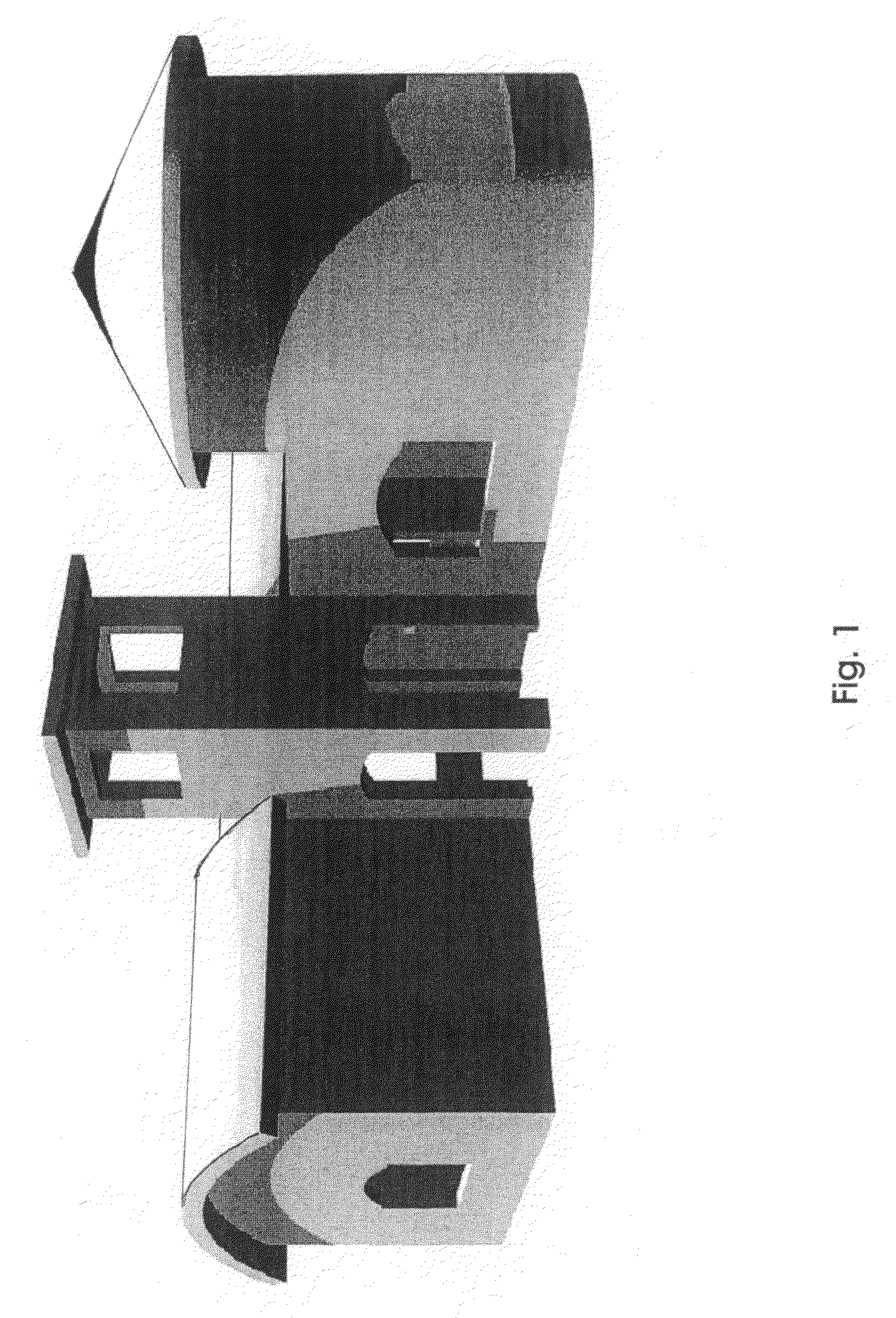
[0008]FIG. 1 shows the rendering of a structure or building created in 3D solid format using an AutoCAD software. The CAD program can also be a program / software, such as AutoCAD, Solidworks, Alibre, Mechanical Desktop, etc.

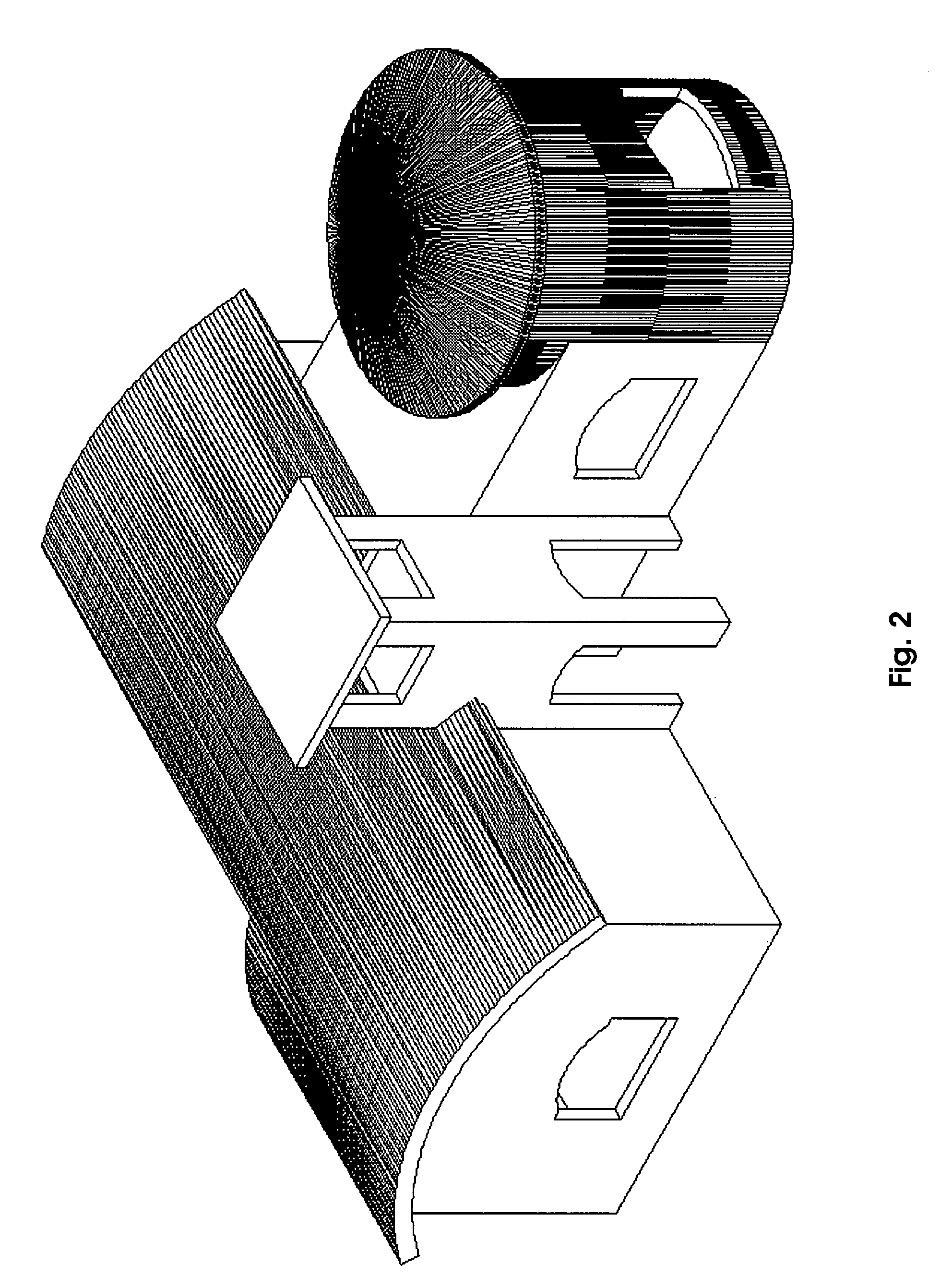
[0009]FIG. 2 shows the solid format of a 3D drawing constructed by Mechanical Desktop by Autodesk. When the building is created, the dimensions of the building are provided to the program by the building designer / architect.

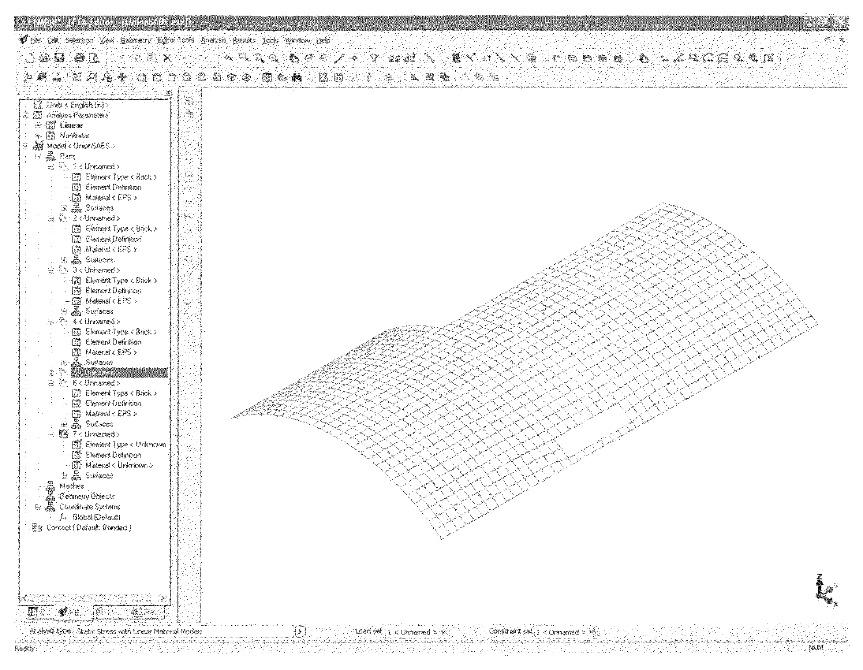
[0010]FIG. 3 shows the exporting of the 3D CAD drawing file using a compatible format that can be exported out of the CAD program and imported by a Finite Element Analysis (FEA) program or software, such as Algor (FIG. 4). Depending on the FEA program, a different output or export format defining the solid model is selected. These formats maybe of the file type that have the extension STEP, IGES and SAT. If the building is to be worked on in pieces, STEP can be used. If the building is to be worked on in one piece or united, IGES can be used. In...


PUM


Abstract

The invention provides a method of analyzing a building made from Expanded Poly Styrene (EPS) which is coated on the inside and outside with Glass Fiber Reinforced Concrete (GFRC) or other strengthening coating. The building is designed in a CAD program. Then, the building is divided up into small volumes in the CAD program or in a Finite Element Analysis program using an automeshing program. Plates are added to the inner and outer surfaces of the volumes using copying and automeshing commands. Appropriate characteristics of the EPS and GFRC are assigned to the volumes and plates. A FEA analysis can then be run.

Description

CROSS-REFERENCE TO RELATED APPLICATIONS[0001]This application is a continuation-in-part if Ser. No. 60 / 848,554, filed Sep. 30, 2006.[0002]This application is related to U.S. Pat. No. 6,721,684, granted to the inventor, in which the core of the composite building was created by using the manual method of dividing the solid core geometry of the CAD model into discrete volumes, such as bricks and tetrahedral elements (FIGS. 67 through 87 of that patent).BACKGROUND OF THE INVENTION[0003]This invention discloses an improvement on U.S. Pat. No. 6,721,684 which disclosed a method of performing the Finite Element Analysis (FEA) of a composite structure using a FEA program, such as Algor FEMPRO. Now, in these programs, the solid, shell, or plate structure can be divided into discrete meshes by a powerful automeshing portion of the program. The program has three choices of meshing—Solid meshing (meshing of the Solid or core), Midplane meshing (meshing at the midplane) and Plate or Shell meshi...

Claims


Application Information

Patent Timeline
Patent Type & Authority Patents(United States)
IPC IPC(8): G06F17/50
CPCG06F17/5004G06F17/5018G06F2217/42G06F2217/44G06F30/13G06F30/23G06F2113/24G06F2113/26
Inventor SAEBI, NASSER
Owner SAEBI NASSER
Why Eureka
Try Eureka