Supercharge Your Innovation With Domain-Expert AI Agents!

Gas turbine engine diffuser and combustion chamber and gas turbine engine comprising same

a technology of gas turbine engines and diffusers, which is applied in the direction of machines/engines, mechanical equipment, lighting and heating apparatus, etc., can solve the problems of affecting the correct operation, the pressure drop between the external wall and the internal wall is not uniform,

Active Publication Date: 2010-11-02
SN DETUDE & DE CONSTR DE MOTEURS DAVIATION S N E C M A
View PDF4 Cites 8 Cited by
  • Summary
  • Abstract
  • Description
  • Claims
  • Application Information

AI Technical Summary

Benefits of technology

The invention proposes a design for a gas turbine engine diffuser that reduces the imbalance between the two diffuser ducts. This is achieved by adding a cowling to the diffuser, which helps to close off the external duct and partially close off the internal duct. The cowling is positioned towards the closed end of the combustion chamber and has a symmetrical body with a flat cross section and a radially internal and external edge. The cowling also has at least one aperture with turned-down edges. The cowling is fixed to the combustion chamber using fixing means positioned on the internal edge. This design helps to improve the performance and efficiency of gas turbine engines.

Problems solved by technology

This imbalance in the pressure drops between the external wall 12 and the internal wall 14 is detrimental to the correct operation of the combustion chamber 10 because the primary jets enter and are diluted better in the region of the external wall 12 than in the region of the internal wall 14.
Furthermore, because the pressure drops available are lower across the internal wall 14, this wall is more difficult to cool.

Method used


Image

  • Gas turbine engine diffuser and combustion chamber and gas turbine engine comprising same
  • Gas turbine engine diffuser and combustion chamber and gas turbine engine comprising same
  • Gas turbine engine diffuser and combustion chamber and gas turbine engine comprising same

Examples


first embodiment

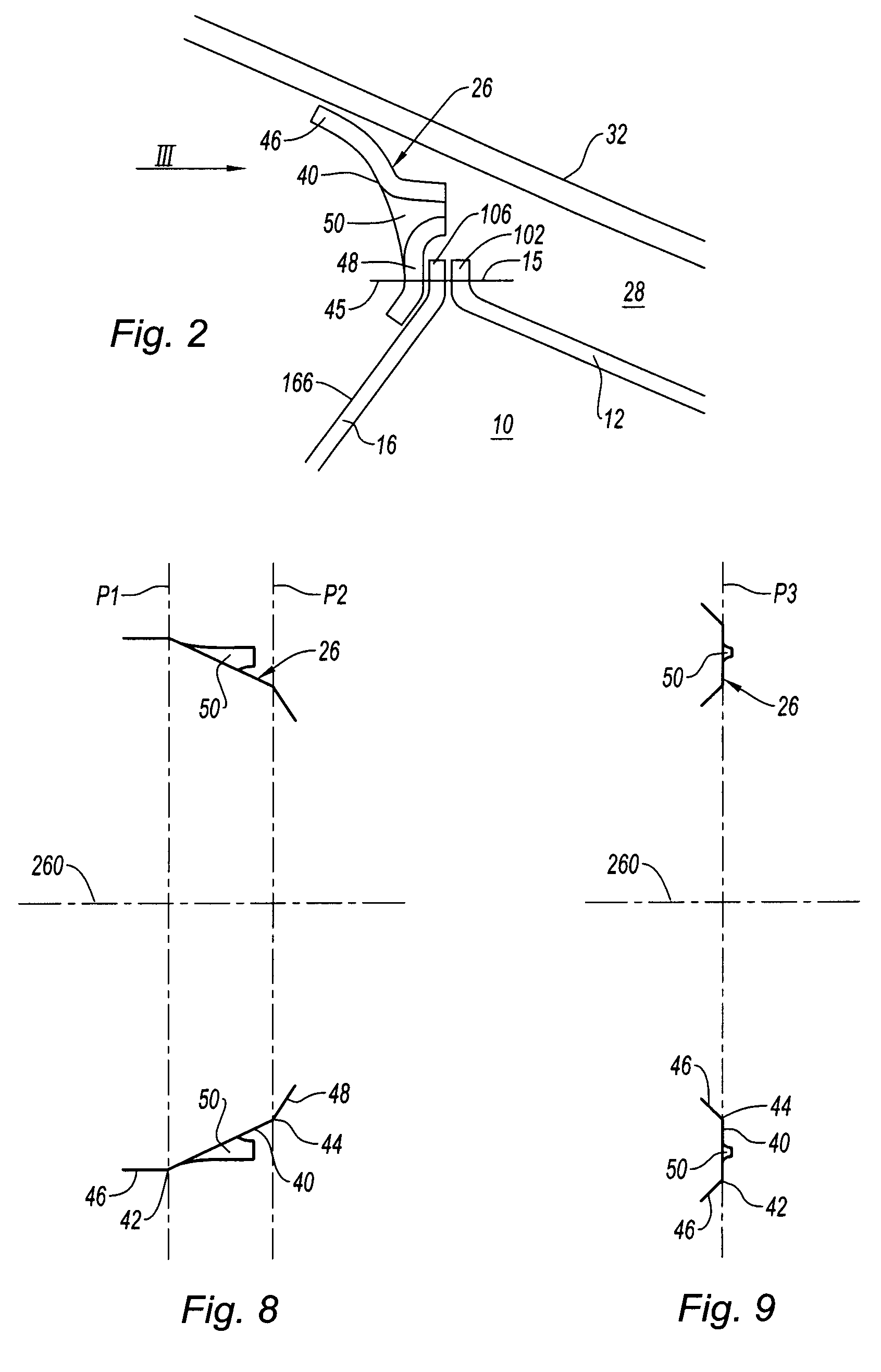
[0040] illustrated more specifically in FIG. 8, the body 40 is in the form of a cone frustum lying between two planes P1 and P2 which are transverse with respect to the cowling axis 260. When the cowling 26 is in place in the diffuser 30, the external edge 46 of the cowling 26 extends substantially toward the upstream end of the diffuser 30, and its internal edge 48 extends substantially toward the cowling axis 260 which then coincides with the axis of the turbojet engine 100.

second embodiment

[0041] illustrated more specifically in FIG. 9, the body 40 is in the form of a portion of a disk contained in a plane P3 that is transverse with respect to the cowling axis 260. When the cowling 26 is in place in the diffuser 30, the external edge 46 and the internal edge 48 of the cowling 26 extend substantially toward the upstream end of the diffuser 30. In addition, when the cowling 26 is in use, the cowling axis 260 and the axis 100 of the turbojet engine coincide.

[0042]According to the first or second embodiments of the cowling 26, this cowling is fixed to the combustion chamber 10.

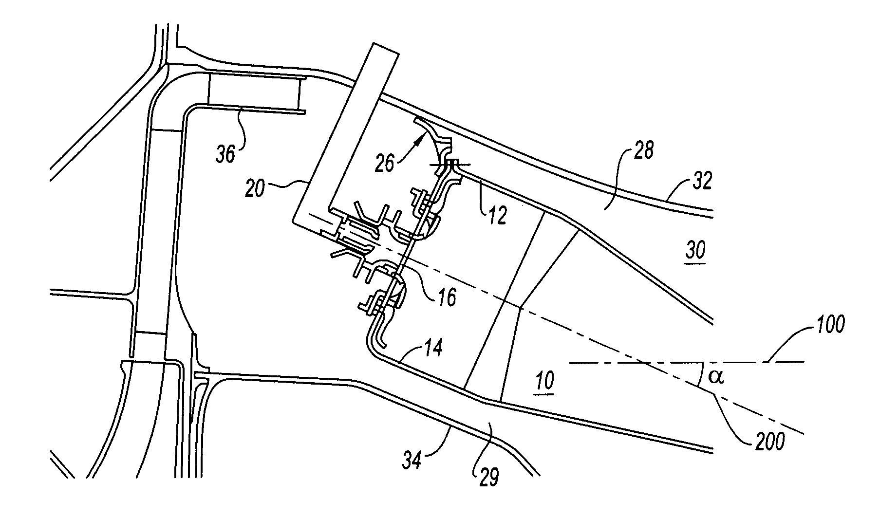
[0043]As illustrated in FIG. 1, the chamber end wall 16 and the external wall 12 are fixed to one another in an airtight manner. In the example illustrated in FIGS. 1 and 2, this fixing is performed using a screwed or bolted connection 15 between a flange 102 of the external wall 12 and a flange 106 of the chamber end wall 16, these two flanges extending radially outward. These flanges may be annula...


PUM


Abstract

A gas turbine engine diffuser defined between an external casing and an internal casing of the engine and supplied with air via an upstream annular diffuser duct is disclosed. The diffuser includes a combustion chamber of the convergent type, forming an external annular duct with the external casing and an internal annular duct with the internal casing, and a cowling partially closing off the external annular duct. The cowling is positioned toward the closed end of the combustion chamber.

Description

BACKGROUND OF THE INVENTION AND DESCRIPTION OF THE PRIOR ART[0001]The present invention relates to the technical field of combustion chambers for gas turbine engines such as turbojet engines. It is aimed in particular at a diffuser comprising a cowling on the combustion chamber.[0002]In everything which follows, the terms “axial”, “radial” and “transverse” correspond respectively to an axial direction, a radial direction, and a transverse plane of the turbojet engine and the terms “upstream” and “downstream” correspond respectively to the direction in which the gases flow through the turbojet engine.[0003]A conventional combustion chamber known as a divergent combustion chamber is illustrated in FIG. 10 which is an axial cross section showing half of the combustion chamber, the other half thereof being symmetric therewith respect to the axis (not depicted) of the engine. The combustion chamber 110 is contained in a diffuser 130 which is an annular space defined between an external c...

Claims


Application Information

Patent Timeline
Patent Type & Authority Patents(United States)
IPC IPC(8): F02C1/00F02G3/00
CPCF02C3/14F23R3/04F23R3/26F23R3/50Y02T50/675Y02T50/60
Inventor COMMARET, PATRICE ANDREDESAULTY, MICHEL ANDRE ALBERTLUNEL, ROMAIN NICOLASSANDELIS, DENIS JEAN MAURICE
Owner SN DETUDE & DE CONSTR DE MOTEURS DAVIATION S N E C M A
Features
  • R&D
  • Intellectual Property
  • Life Sciences
  • Materials
  • Tech Scout
  • Unparalleled Data Quality
  • Higher Quality Content
  • 60% Fewer Hallucinations
Learn More