Drifting kart

a kart and kart technology, applied in the direction of bicycles, transportation and packaging, wheelchairs/patient transportation, etc., can solve the problems of affecting the grip of the rear tire, the speed limit of the kart may not be more than 15, and the rear tire must slid

Active Publication Date: 2010-11-02
KERMANI ALI
View PDF8 Cites 72 Cited by
  • Summary
  • Abstract
  • Description
  • Claims
  • Application Information

AI Technical Summary

Benefits of technology

[0009]In a further embodiment, the two caster wheels are mounted to the chassis via a rotatable member that is connected to the hand lever, and rotation of the hand lever rotates the caster wheels from a first position where the caster wheels are aligned so that the weight on the caster wheels limits the ability of the caster wheels to swivel about their swivel axes, to a second position where the caster wheels are aligned so that they are free to swivel about their swivel axes.

Problems solved by technology

Karts vary widely in speed and can reach speeds exceeding 160 miles per hour, while karts intended for the general public may be limited to speeds of no more than 15 miles per hour.
The lack of a differential means that one rear tire must slide while cornering.
During a hand brake drift, the hand brake lever is used to stop the rear wheels, upsetting their grip and causing them to drift.

Method used


Image

  • Drifting kart
  • Drifting kart
  • Drifting kart

Examples


Embodiment Construction

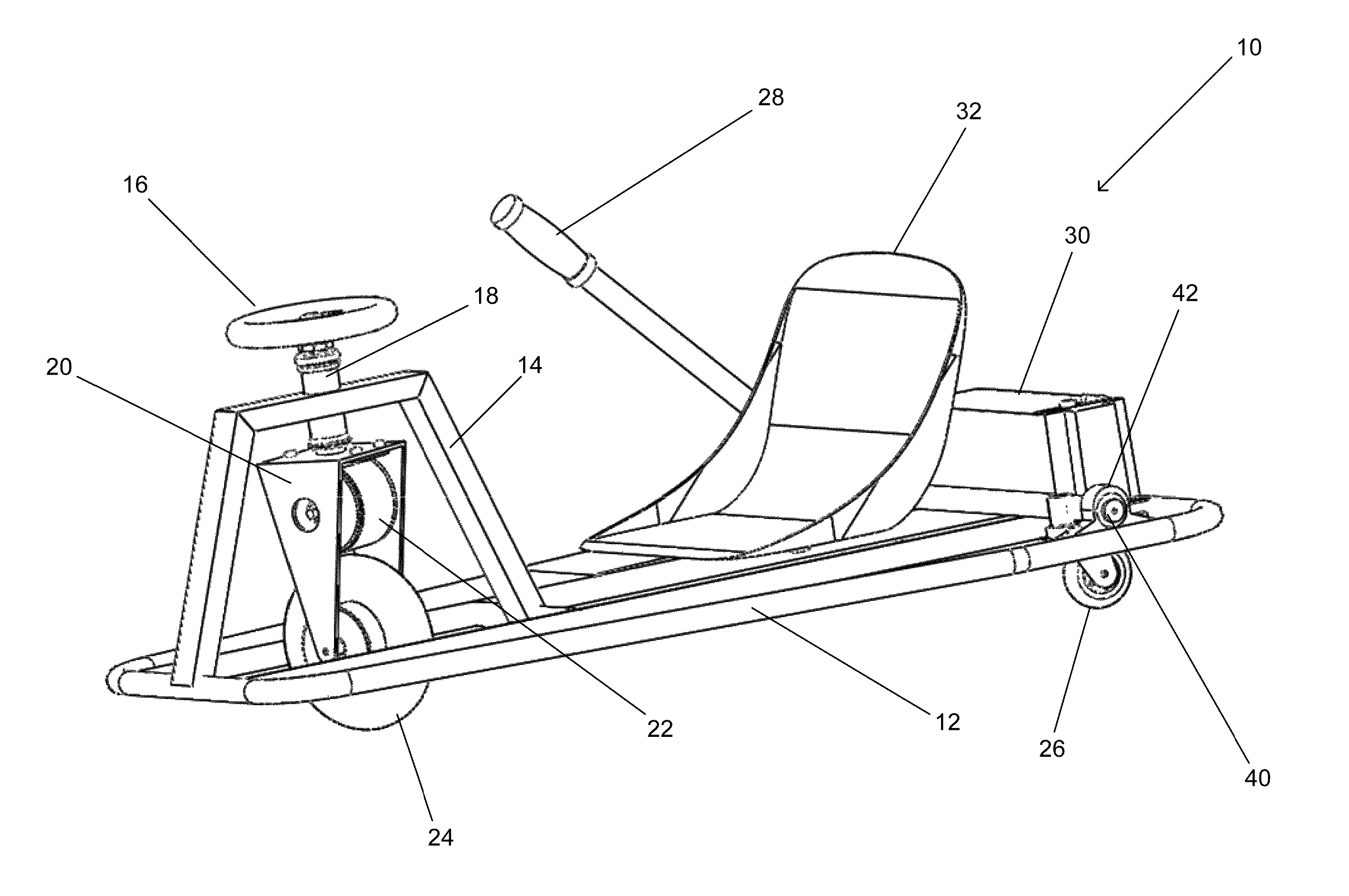
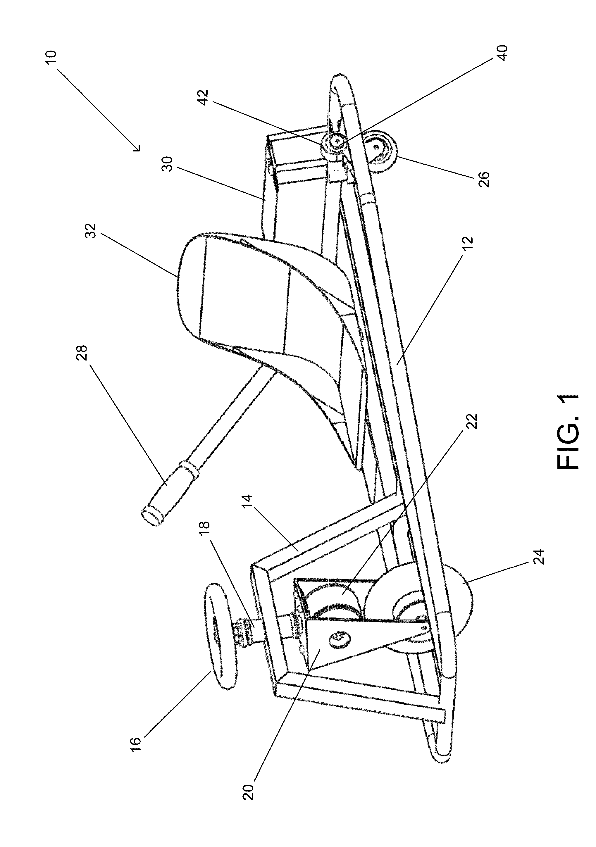
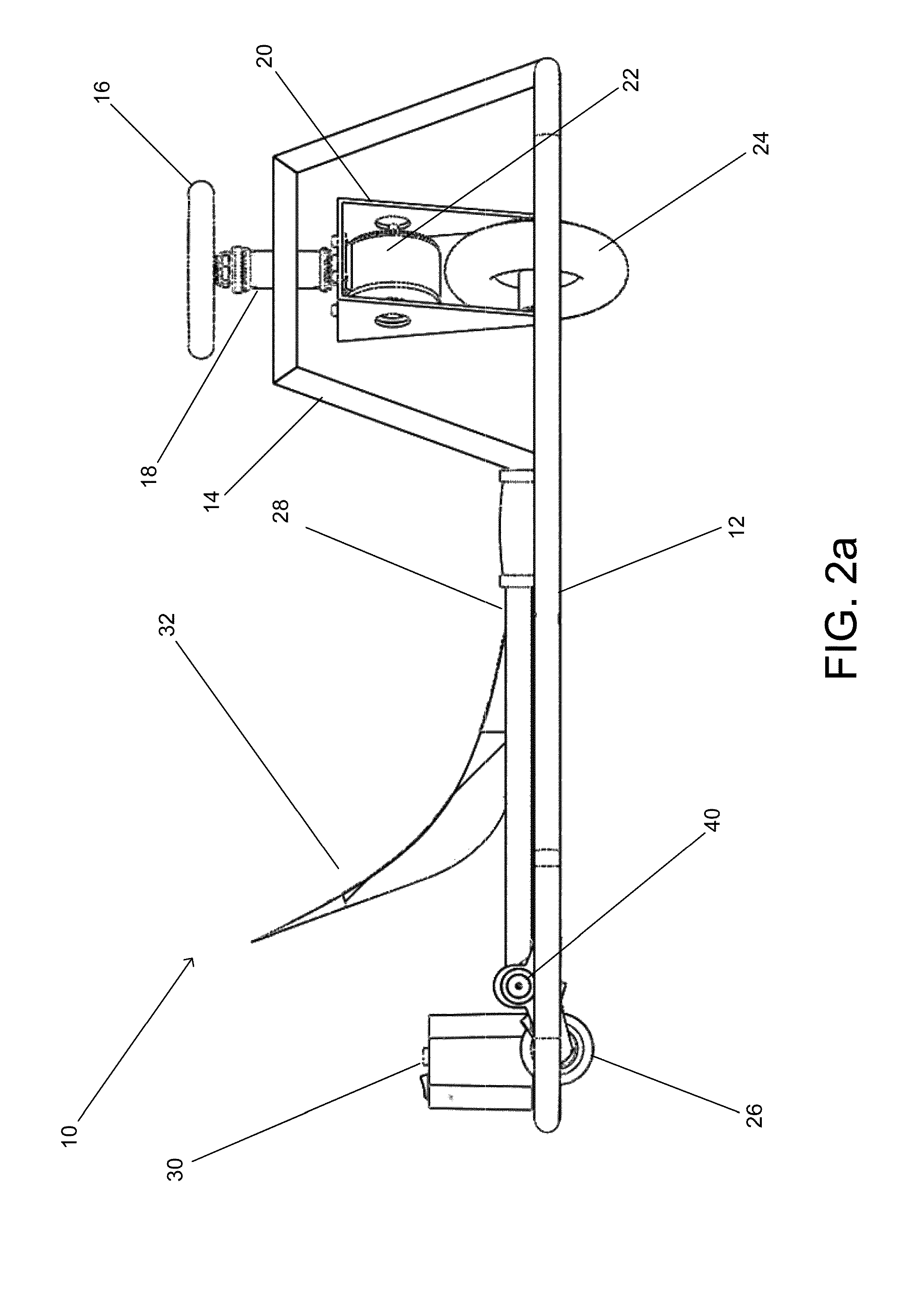
[0031]Turning now to the drawings, drifting karts that are front wheel drive and include rear caster wheels that can be dynamically engaged to induce and control drift during a turn in accordance with embodiments of the invention are illustrated. A caster wheel typically includes a wheel configured to rotate around a rotational axis and a fork supporting the wheel, which enables the wheel to swivel around a swivel axis. When the caster wheels of the drifting kart contact a track surface and the caster wheels are free to swivel around their swivel axes, the caster wheels are considered “engaged” and the kart can be steered into a drift. The caster wheels can be “disengaged” to steer the kart normally by either limiting the extent to which the caster wheels can swivel or by shifting the caster wheels so that they do not contact the track surface.

[0032]In a number of embodiments, a hand lever controls the engagement of the caster wheels and can be used by a driver to induce and control...


PUM


Abstract

Drifting karts in accordance with embodiments of the invention are described that include a front wheel drive train and rear caster wheels that can be dynamically engaged to induce and control drift during a turn. One embodiment of the invention includes a chassis to which a steering column is mounted, where the steering column includes at least one front steerable wheel configured to be driven by an electric motor, a battery housing mounted to the chassis, where the battery housing contains a controller and at least one battery, wiring configured to provide power from the at least one battery to the electric motor, two caster wheels mounted to the chassis, where each caster wheel is configured to rotate around a rotational axis and swivel around a swivel axis, and a hand lever configured to dynamically engage the caster wheels to induce and control drift during a turn.

Description

RELATED APPLICATIONS[0001]This application claims priority to U.S. Provisional Application No. 61 / 082,014 filed Jul. 18, 2008, the entire disclosure of which is hereby incorporated by reference.FIELD OF THE INVENTION[0002]The present invention relates to the field of motorized vehicles and, more specifically, to a kart type vehicle used for racing, and recreational entertainment.BACKGROUND OF THE INVENTION[0003]Karting or kart racing is a popular open-wheeled motor sport with simple, small four wheeled vehicles called karts, go-karts, or gearbox / shifter karts depending on the design. Karts vary widely in speed and can reach speeds exceeding 160 miles per hour, while karts intended for the general public may be limited to speeds of no more than 15 miles per hour. 2-stroke or 4-stroke engines are typically used to power karts. However, a number of karts are powered by electric motors including DC electric motors.[0004]Karts are typically rear wheel drive and are steered using the fron...

Claims


Application Information

Patent Timeline
Patent Type & Authority Patents(United States)
IPC IPC(8): B62D61/06
CPCA63G25/00B62D21/183B62D39/00B62D61/08B60K7/0007B62D9/00B62D63/02B62D17/00A61G5/1051A61G5/047B62B5/0026B62K5/025
Inventor KERMANI, ALI
Owner KERMANI ALI
Why Eureka
Try Eureka