Light monitoring device for an elevator system

a technology for monitoring devices and elevator systems, applied in the direction of optical detection, elevators, transportation and packaging, etc., can solve the problems of high amount of information that needs to be analyzed and evaluated by the evaluation unit, complicated three-dimensional semiconductor sensors enabling three-dimensional detection of image information,

Inactive Publication Date: 2010-11-02
INVENTIO AG
View PDF16 Cites 5 Cited by
  • Summary
  • Abstract
  • Description
  • Claims
  • Application Information

AI Technical Summary

Benefits of technology

[0006]In comparison to the known system described in EP 1 345 444 A1 the monitoring device according to the present invention does not require an extra light source within the housing of a sensor unit. It is sufficient to use the light emitted by a foreign light source, e.g. the landing light, the car light or even the car emergency light.
[0007]The data information used for monitoring the elevator system is based on the filtered contrast of the light, i.e. a sub-set of two-dimensional information. Hence, less data processing power is necessary to process the light information received by the sensor unit. As such, part of the evaluation can be integrated in the sensor unit. Preferably, the chip of the sensor unit includes the evaluation unit. In other words, the algorithm for evaluating the contrast information is implemented at least partly on the sensor chip itself and only minimal further processing is necessary. Only one chip need be used.
[0008]According to the present invention the light information detected does not constitute a full image, but only a subset of an image gradient, gradient orientation or gradient evaluation. For example, the sensor chip outputs only most significant contrast gradients as image features and so part of the contrast analysis is made on the sensor chip.

Problems solved by technology

Three-dimensional semiconductor sensors enabling three-dimensional detection of image information are complicated and costly.
As a further disadvantage a high amount of information needs to be analyzed and evaluated by the evaluation unit.

Method used


Image

  • Light monitoring device for an elevator system
  • Light monitoring device for an elevator system
  • Light monitoring device for an elevator system

Examples


Embodiment Construction

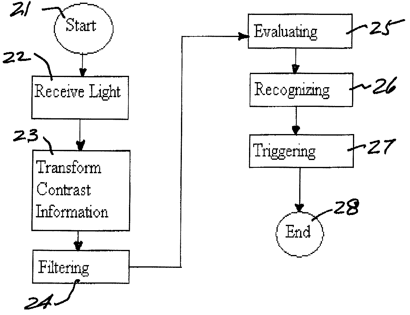
[0024]The following detailed description and appended drawings describe and illustrate various exemplary embodiments of the invention. The description and drawings serve to enable one skilled in the art to make and use the invention, and are not intended to limit the scope of the invention in any manner. In respect of the methods disclosed, the steps presented are exemplary in nature, and thus, the order of the steps is not necessary or critical.

[0025]According to the following example a preferred embodiment of the monitoring device and monitoring method according to the present invention is described:

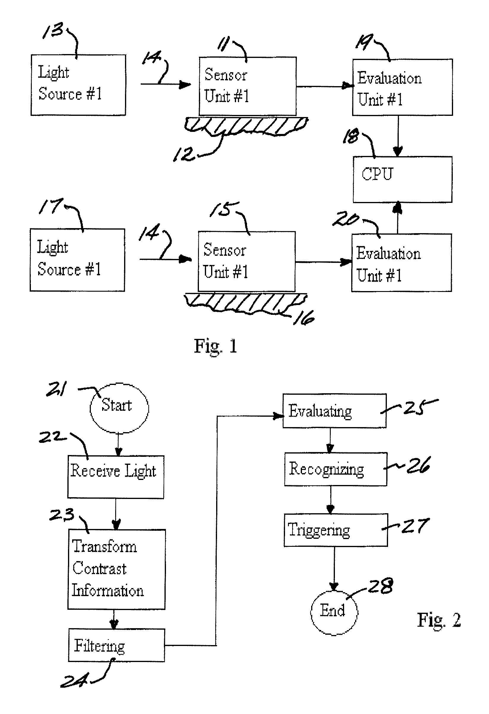
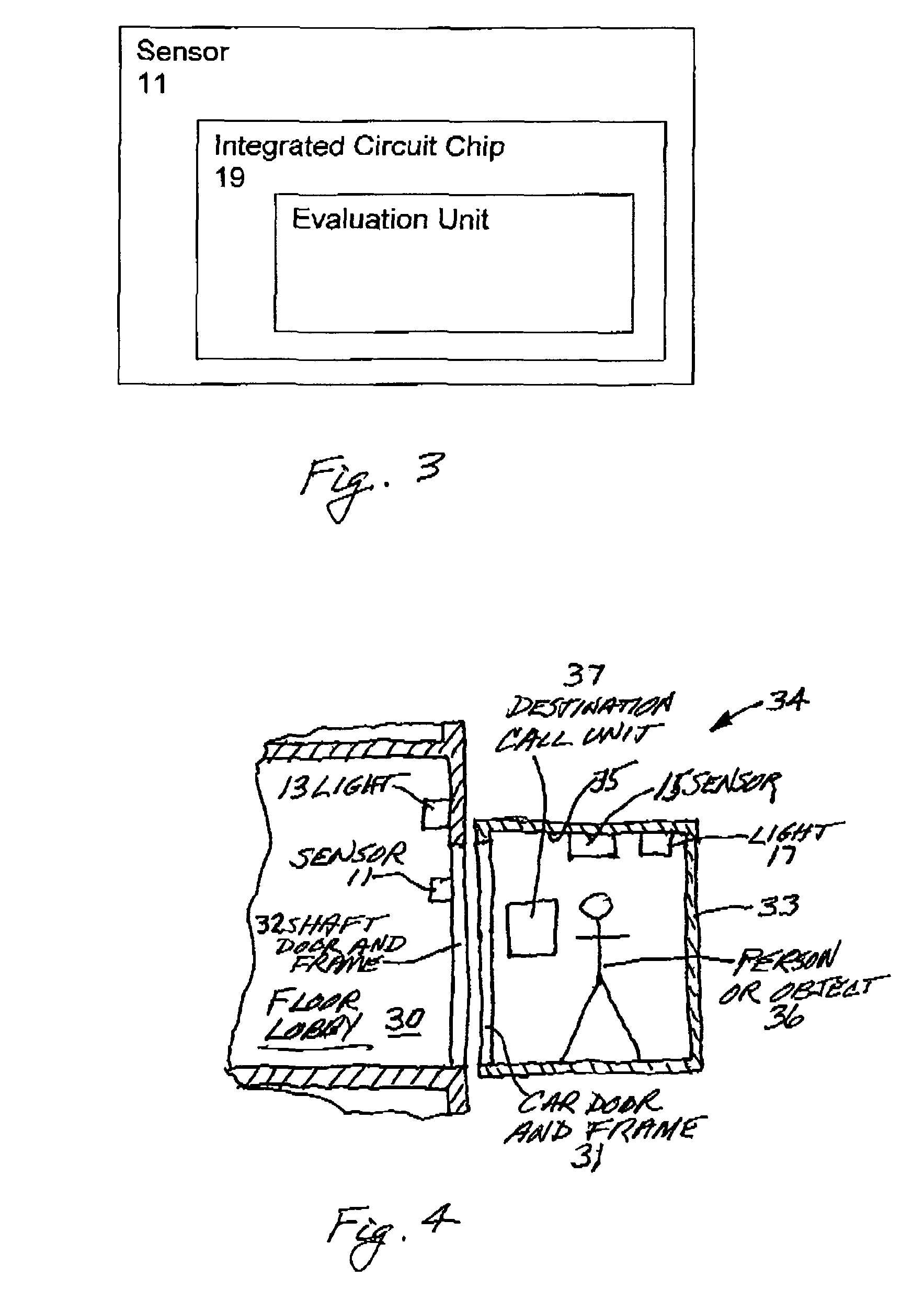
[0026]An elevator system of a building comprises a plurality of elevators for transporting passengers. As shown in FIG. 1, at each floor of the building a first sensor unit 11 is positioned in the vicinity of each elevator door frame 12 to monitor a predetermined area in front of the elevator doors. Close to the first sensor unit 11 a landing light 13 is disposed and emits light 14, wh...


PUM


Abstract

The present invention relates to a monitoring device for a elevator system, including an optical sensor unit, which receives light emitted by a external light source existing in the vicinity of the elevator system and which transforms the light into contrast information and an evaluation unit, which evaluates the contrast information in order to monitor the elevator system. The present invention relates further to a method for monitoring a elevator system, including the steps of receiving light emitted by a external light source existing in the vicinity of the elevator system, transforming the light into contrast information, evaluation of the contrast information in order to monitor the elevator system, recognizing a situation of the elevator system and triggering of a reaction adapted to the situation.

Description

FIELD OF THE INVENTION[0001]The present invention relates to a monitoring device for an elevator system comprising an optical sensor unit and an evaluation unit. The optical sensor unit receives and transforms light into light information in order to monitor the elevator system. Furthermore, the present invention relates to a method for monitoring the elevator system.BACKGROUND OF THE INVENTION[0002]A system for monitoring an elevator door is shown in EP 1 345 444 A1, which comprises a three-dimensional semiconductor sensor and a processing device. The three-dimensional semiconductor sensor includes a light source radiating light in a specific range, wherein the light source is preferably a laser diode. The light emitted by the light source is reflected by the elevator door. A sensor group mounted in the region of the elevator door receives the light reflected by the elevator door. Further, the processing unit converts the light information into three-dimensional image information, ...

Claims


Application Information

Patent Timeline
Patent Type & Authority Patents(United States)
IPC IPC(8): B66B1/34
CPCB66B1/34B66B5/0018G01V8/10
Inventor ROUSSEL, FRANK
Owner INVENTIO AG
Why Eureka
Try Eureka