Aircraft luggage compartment

Inactive Publication Date: 2010-11-02
AIRBUS SAS
View PDF23 Cites 16 Cited by
  • Summary
  • Abstract
  • Description
  • Claims
  • Application Information

AI Technical Summary

Benefits of technology

[0003]It is an object to provide for

Problems solved by technology

Since the luggage compartments may not be suspended so high and thus prevent shorter individuals from storing baggage in the lu

Method used


Image

  • Aircraft luggage compartment
  • Aircraft luggage compartment
  • Aircraft luggage compartment

Examples


Example

[0030]The same reference numbers for identical or similar elements are used in the following figure description.

DETAILED DESCRIPTION

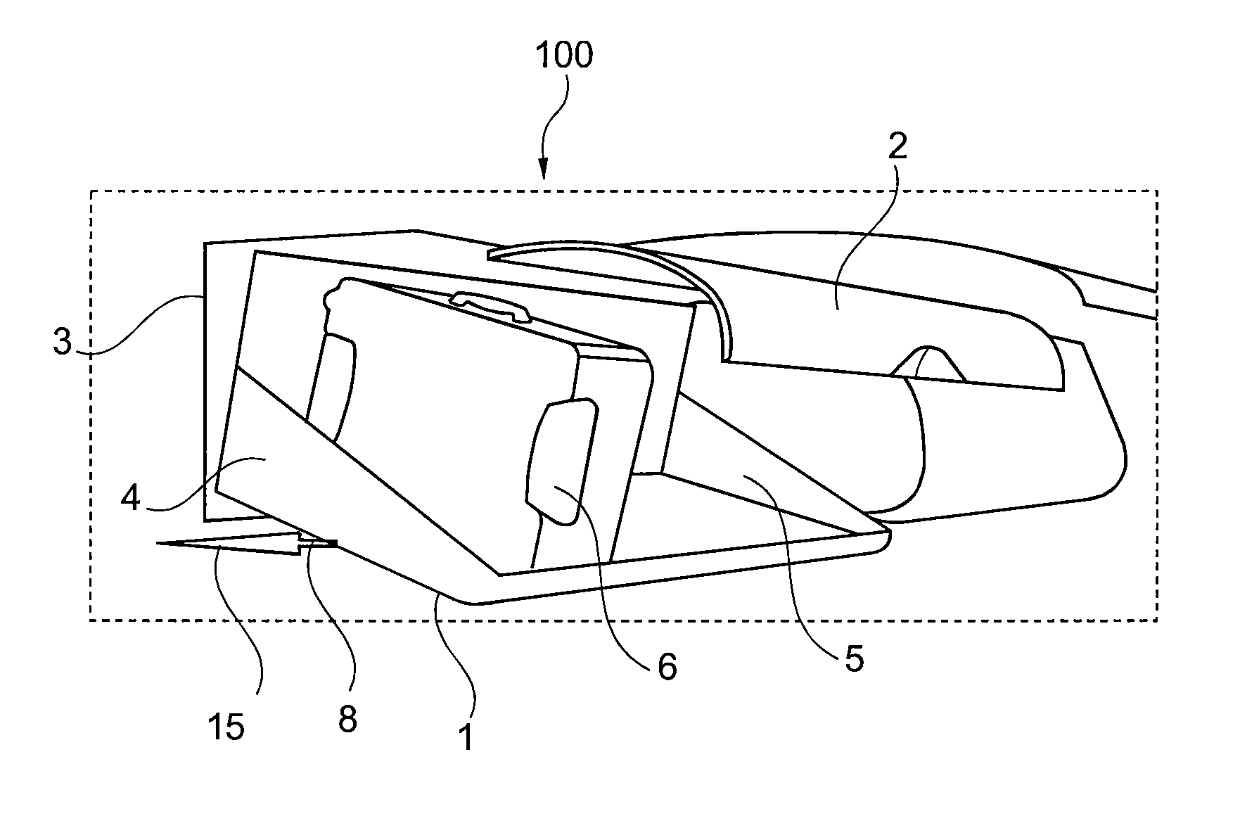
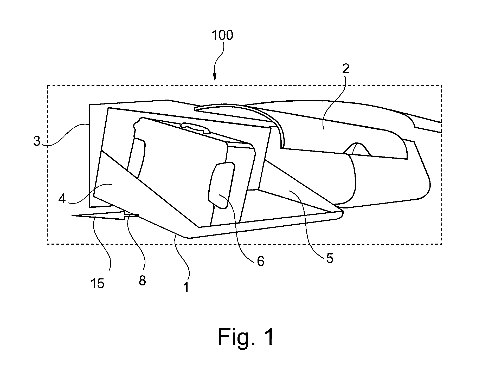
[0031]The examples described and drawings rendered are illustrative and are not to be read as limiting the scope of the invention as it is defined by the appended claims. FIG. 1 shows a first perspective, diagrammatic view of a luggage compartment according to one embodiment. As evident from FIG. 1, the luggage compartment 100 has a tilting floor 1 with a first lateral wall 4 and a second lateral wall 5. The two lateral walls 4, 5 are rigidly joined by way of a rotational axis (not shown on FIG. 1), which may be located on the tilting floor 1, for example. The rotational axis is part of a suspension device 8, which is designed for turning the tilting floor 1, and consequently pivoted (e.g., in corresponding side panels). The rotational axis rigidly joins the first and second lateral walls, thereby yielding a stable structure that is able to withstand st...


PUM


Abstract

A luggage compartment for aircraft comprises a tilting floor, a flap and a suspension device. The tilting floor is designed for holding carry-on baggage and the like, and may be locked in an initial position and may be tilted to another position for easier loading or unloading. The loading edge height may be substantially lower than the initial height of the closed luggage compartment. For example, an interlocking mechanism may couple the opening and closing of a flap and the tilting of the floor from an initial position to the tilted position, such as a three-position handle that prevents release of the tilting floor until the flap is unlatched.

Description

FIELD OF THE INVENTION[0001]This field relates to luggage compartments for aircraft. In particular, this field relates to a luggage compartment for an aircraft, an aircraft comprising such a luggage compartment, the use of a luggage compartment in an aircraft, and a method for loading baggage in a luggage compartment.BACKGROUND[0002]Luggage compartments in aircraft are used for stowing and keeping carry-on baggage, clothing and the like. The luggage compartments are located to the left and right of the aisle at or slightly above passenger head level. Since the luggage compartments may not be suspended so high and thus prevent shorter individuals from storing baggage in the luggage compartment, taller individuals often find it impossible to stand up straight under many conventionally used compartments.SUMMARY OF THE INVENTION[0003]It is an object to provide for improved baggage stowage in aircraft.[0004]According to an embodiment, a luggage compartment for aircraft comprises a tiltin...

Claims


Application Information

Patent Timeline
IPC IPC(8): B64C1/20
CPCB64D11/003
Inventor FELDKIRCHNER, ERICHBOCK, THOMAS M.
Owner AIRBUS SAS
Why Eureka
Try Eureka