Small form factor pluggable (SFP) optical transceiver module and method

a pluggable, small technology, applied in the field of optical fiber communication systems, can solve the problems of lc connector and mtrj connector not being suited to terminating the end of pofs

Inactive Publication Date: 2010-11-02
AVAGO TECH WIRELESS IP SINGAPORE PTE
View PDF24 Cites 137 Cited by
  • Summary
  • Abstract
  • Description
  • Claims
  • Application Information

AI Technical Summary

Problems solved by technology

The LC connector and MTRJ connector are not suited for terminating the ends of POFs because of the large diameter of this type of fiber.

Method used


Image

  • Small form factor pluggable (SFP) optical transceiver module and method
  • Small form factor pluggable (SFP) optical transceiver module and method
  • Small form factor pluggable (SFP) optical transceiver module and method

Examples


Embodiment Construction

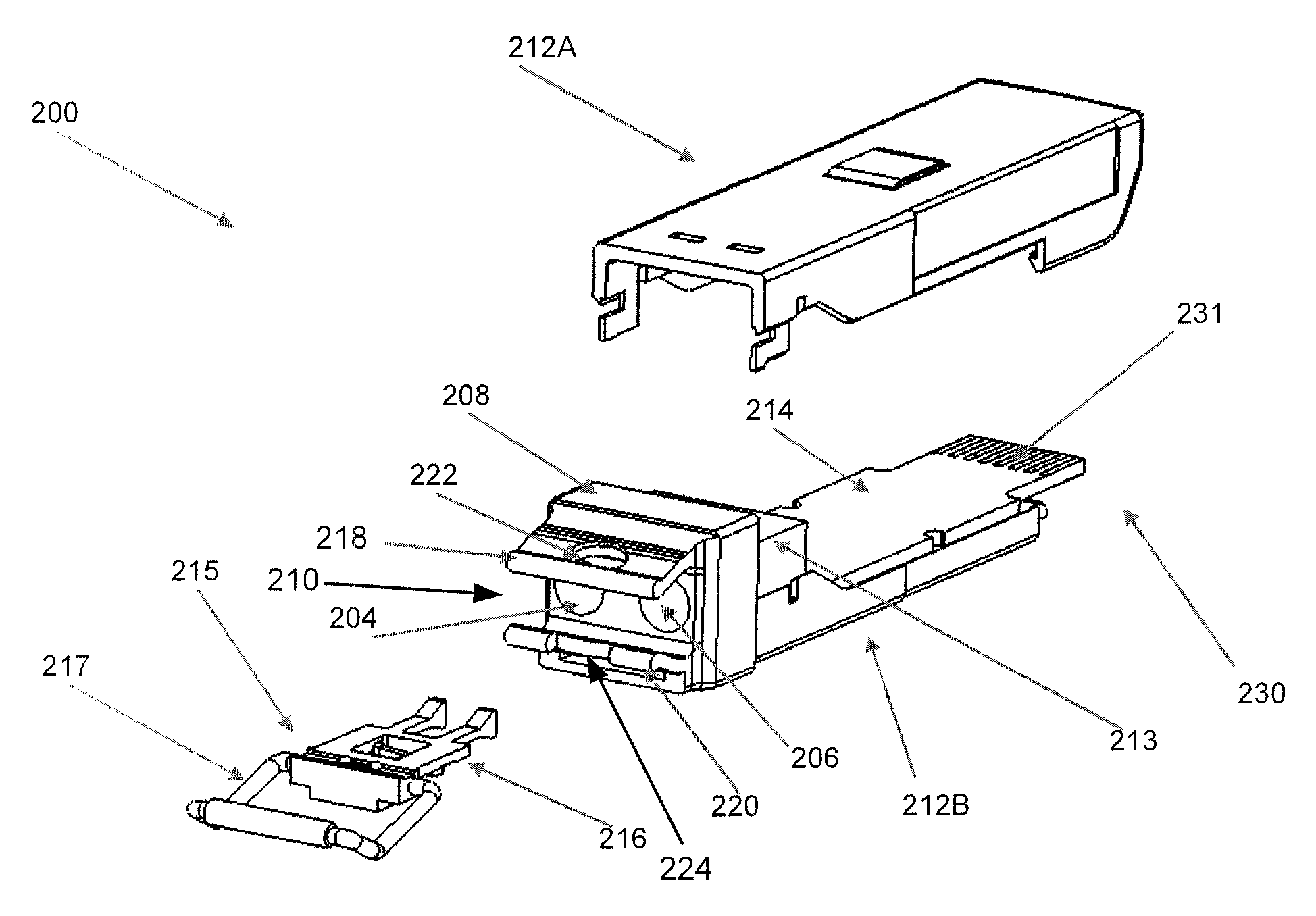
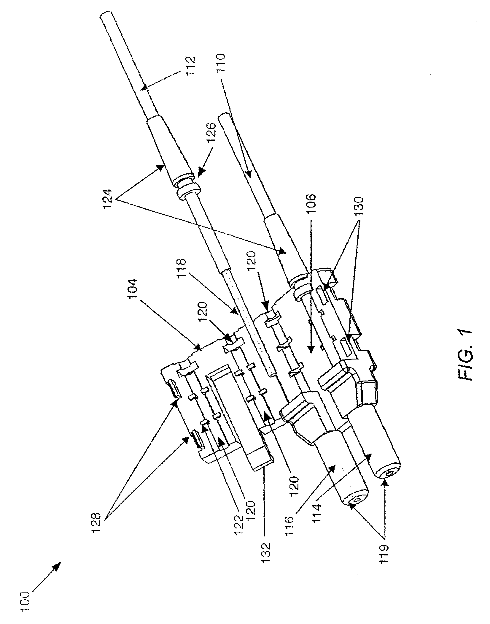
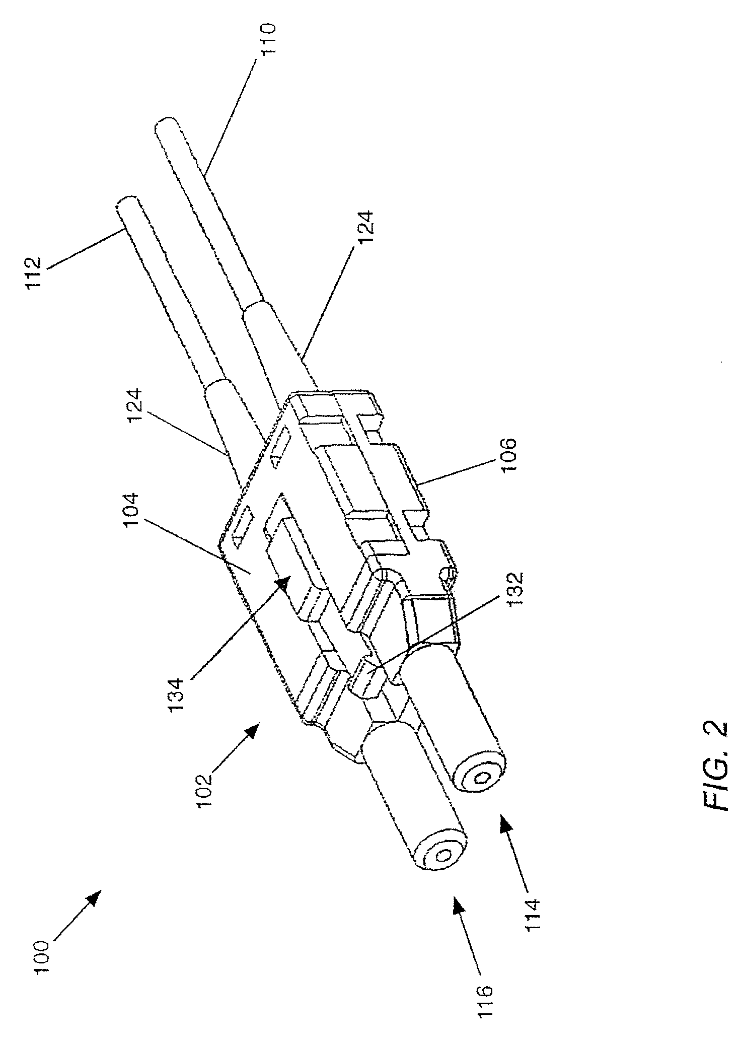
[0024]Various embodiments of a duplex fiber optic connector 100 (FIGS. 1-3) and of a SFP optical transceiver module 200 (FIGS. 4-10) are described herein. Prior to describing the duplex fiber optic connector module 100, a detailed description of the SFP optical transceiver module 200 will be provided.

[0025]FIG. 7 illustrates a perspective view of the SFP optical transceiver module 200 in its partially disassembled form. In accordance with this embodiment, the SFP optical transceiver module 200 includes a duplex receptacle 208, an upper housing portion 212A, a lower housing portion 212B, an optical assembly 213, an electrical assembly 214, and a latching mechanism 215. The upper and lower housing portions 212A and 212B are pressed together to cause locking features on the upper and lower housing portions 212A and 212B to interlock. In accordance with this embodiment, the electrical assembly 214 comprises a PCB having a plug end 230 with electrical contacts 231 located thereon. As wil...


PUM


Abstract

A small form factor pluggable (SFP) optical transceiver module and method for performing optical communications are provided. The SFP optical transceiver module has a housing to which a duplex receptacle is secured. The duplex receptacle has a C-shaped opening, the upper and lower portions of which are defined by upper and lower flexible retaining elements for receiving and retaining a duplex optical connector therein. An electrical assembly of the module is secured within the transceiver module housing. The electrical assembly comprises a PCB, the back end of which is configured as a plug end for removably plugging the PCB into a receptacle of an external communications management system.

Description

CROSS-REFERENCE TO RELATED APPLICATIONS[0001]This application is a continuation-in-part application of a U.S. nonprovisional application having Ser. No. 12 / 040,986, filed on Mar. 3, 2008, and entitled “OPTICAL TRANSCEIVER MODULE AND DUPLEX FIBER OPTIC CONNECTOR”, which is incorporated by reference herein in its entirety and to which priority is claimed.TECHNICAL FIELD OF THE INVENTION[0002]The invention relates to optical fiber communications systems, and more particularly, to a small form factor pluggable (SFP) optical transceiver module and method.BACKGROUND OF THE INVENTION[0003]In optical communications systems, an optical link generally comprises an optical transmitter and an optical receiver that are connected to each other by a fiber optic cable comprising one or more optical fibers. The optical transmitter generally includes one or more light sources, such as, for example, one or more light-emitting diodes (LEDs) or laser diodes, which convert an electrical data signal into ...

Claims


Application Information

Patent Timeline
Patent Type & Authority Patents(United States)
IPC IPC(8): G02B6/36H04B10/24H04B10/00
CPCG02B6/387G02B6/3878G02B6/3887G02B6/4246G02B6/4292G02B6/02033G02B6/3851G02B6/3893G02B6/4284G02B6/4261
Inventor WONG, TOM SHEAU TUNGVAN HAASTEREN, ADRIANUSLIM, TZE WEI
Owner AVAGO TECH WIRELESS IP SINGAPORE PTE
Why Eureka
Try Eureka