Input and output driver circuits for differential signal transfer, and differential signal transfer apparatus and methods

a technology of differential signal and input driver circuit, applied in the field of differential signal transfer, can solve problems such as troublesome appliances with limited available space resources

Active Publication Date: 2010-11-02
SAMSUNG ELECTRONICS CO LTD
View PDF8 Cites 40 Cited by
  • Summary
  • Abstract
  • Description
  • Claims
  • Application Information

AI Technical Summary

Problems solved by technology

This can prove troublesome in appliances having limited available space resources.

Method used


Image

  • Input and output driver circuits for differential signal transfer, and differential signal transfer apparatus and methods
  • Input and output driver circuits for differential signal transfer, and differential signal transfer apparatus and methods
  • Input and output driver circuits for differential signal transfer, and differential signal transfer apparatus and methods

Examples


Embodiment Construction

[0038]The present invention will now be described more fully with reference to the accompanying drawings, in which exemplary embodiments of the invention are shown. The invention may, however, be embodied in many different forms and should not be construed as being limited to the embodiments set forth herein.

[0039]Embodiments of the invention will now be described with reference to the drawings.

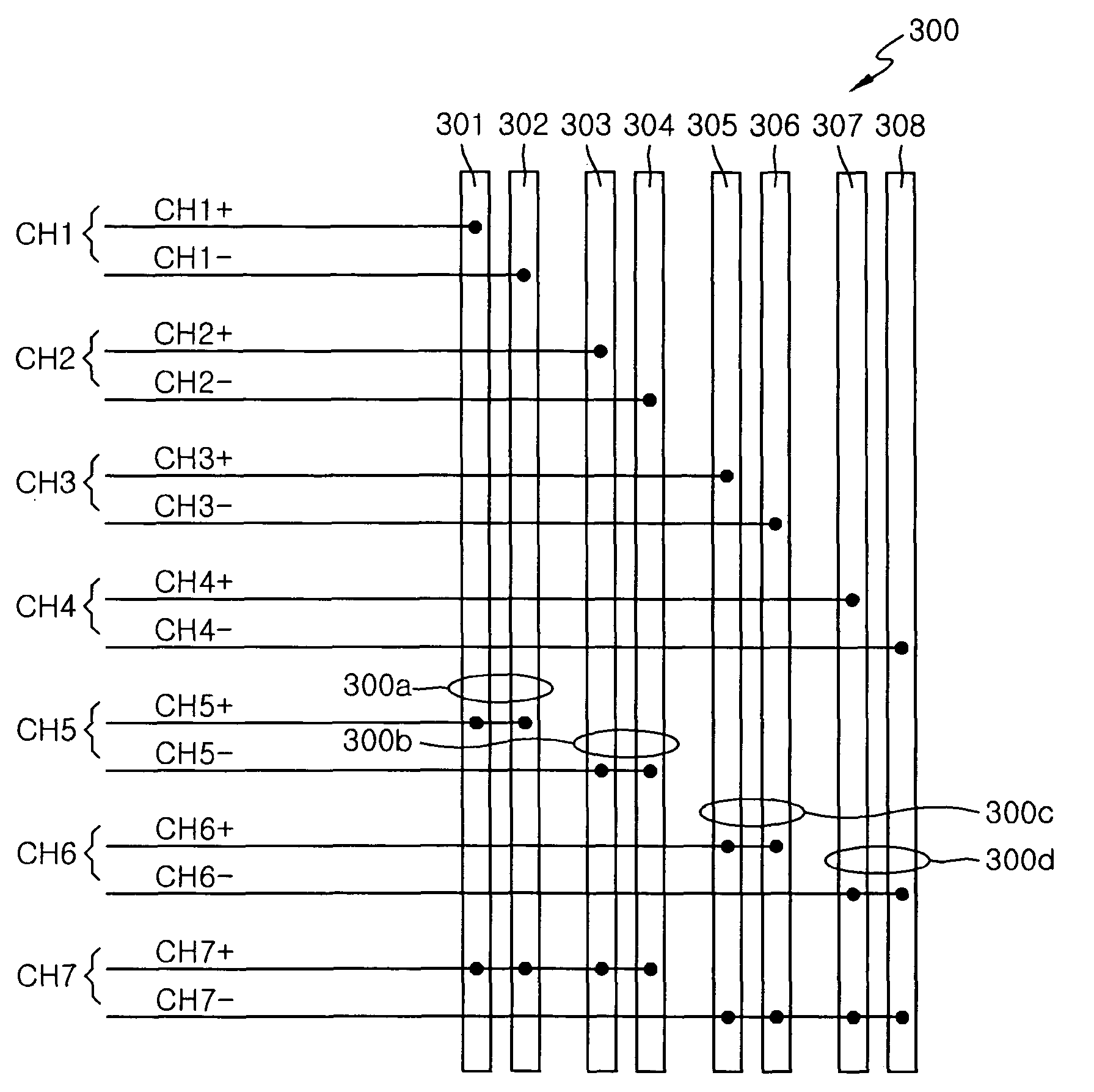
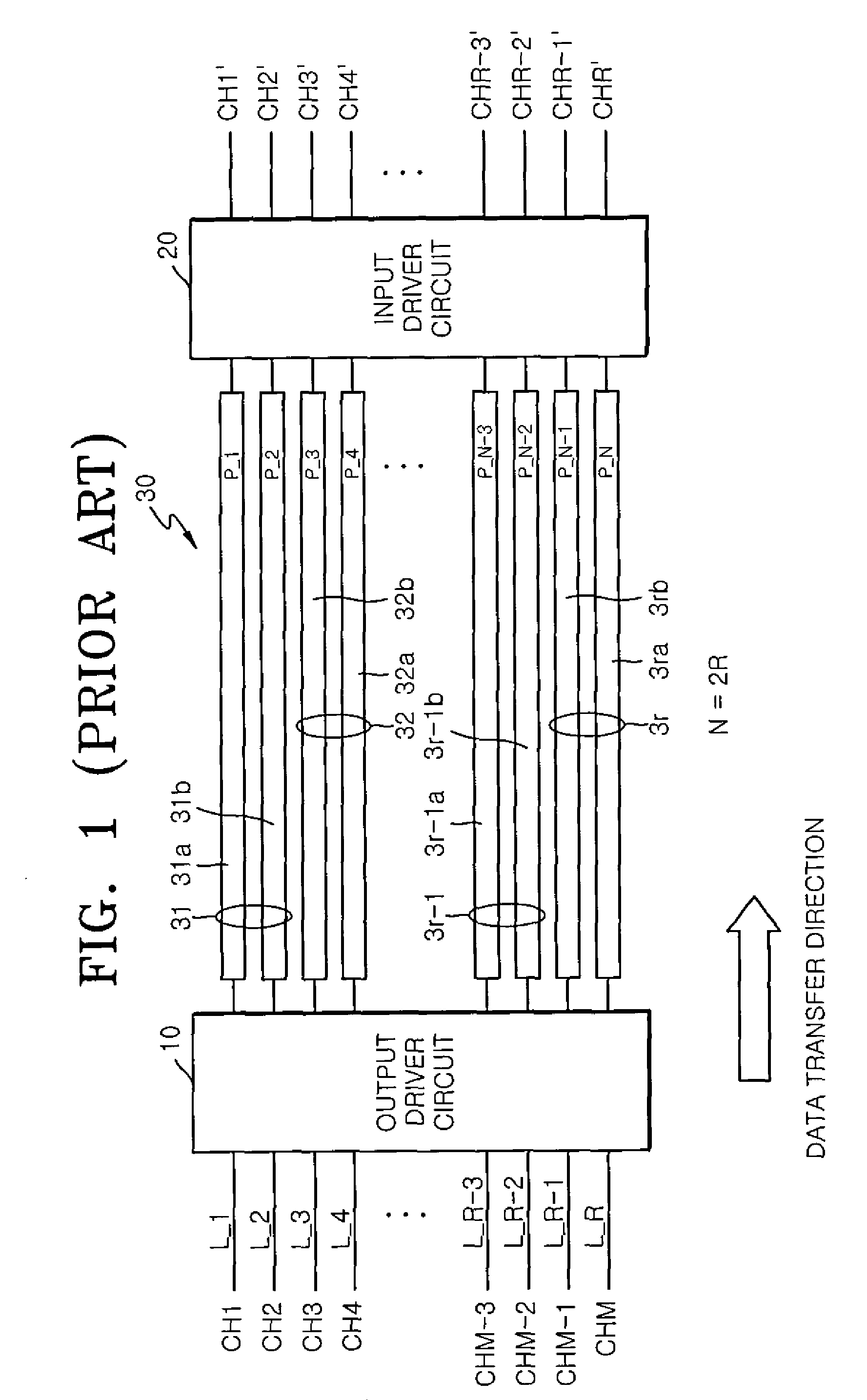
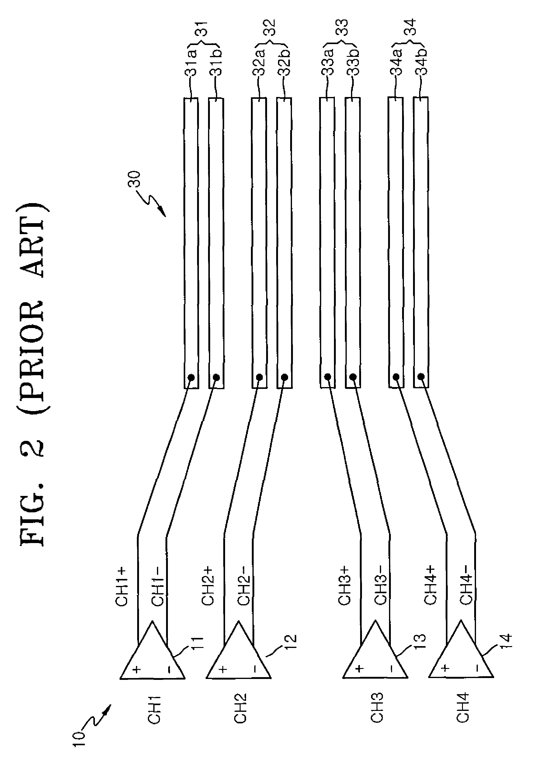
[0040]Referring initially to FIG. 4, an output driver circuit 100 receives R input binary (0 and 1) channel signals CH1 through CH2M−1 (where R=2M−1), and outputs corresponding differential signals on N signal lines 301 through 30N (where N=2M=R+1). The signal lines 301 through 30N are collectively referred to herein as an interconnection unit 300. Also, in the figure, the input channel lines are denoted by reference numbers L_1 though L_2M−1, and the differential lines are denoted by reference numbers P_1 through P_N.

[0041]The output driver circuit 100 converts the channel signals CH1 throug...


PUM


Abstract

In one aspect, a differential signal transfer method is provided which includes converting 2M−1 original signals into 2M−1 differential signal pairs, where M is an integer of 2 or more, and wherein each pair consists of a first differential signal and a second differential signal having opposite phases, and transferring the 2M−1 differential signal pairs to 2M signal lines such that each of the 2M signal lines includes overlapping differential signals among the first differential signals and the second differential signals of the 2M−1 differential signal pairs.

Description

BACKGROUND OF THE INVENTION[0001]1. Field of the Invention[0002]The present invention generally relates to differential signal transfer, and more particularly, the present invention relates to input driver circuits and output driver circuits for transferring differential signals, and to differential signal transfer apparatus and methods related thereto.[0003]A claim of priority is made to Korean Patent Application No. 10-2006-0073459, filed on Aug. 10, 2006, in the Korean Intellectual Property Office, the disclosure of which is incorporated herein in its entirety by reference.[0004]2. Description of the Related Art[0005]Differential signal transfer is generally characterized by the utilization of two physical signal lines to transfer one bit of data. The two signal lines carry respective signals which are inverted relative to one another to denote bit information, e.g., one signal line may carry a negative (−) signal, while the other signal line may carry a positive (+) signal. When...

Claims


Application Information

Patent Timeline
Patent Type & Authority Patents(United States)
IPC IPC(8): H04B3/46H04B17/00H04Q1/20
CPCH04L25/0272G09G3/20H04L12/02H04L69/32
Inventor LEE, HEE-SEOKMIN, SUNG-HWAN
Owner SAMSUNG ELECTRONICS CO LTD
Why Eureka
Try Eureka