System for monitoring sensor outputs of a gas turbine engine

a gas turbine engine and sensor output technology, applied in the direction of registering/indicating the working of vehicles, testing/calibration of speed/acceleration/shock measurement devices, amplifier modifications to reduce noise influence, etc., can solve the problem of preventing satisfactory operation of the engine, abnormal values of control parameters, and inability to detect faults promptly

Inactive Publication Date: 2010-11-02
HONDA MOTOR CO LTD
View PDF33 Cites 22 Cited by
  • Summary
  • Abstract
  • Description
  • Claims
  • Application Information

AI Technical Summary

Benefits of technology

[0007]In view of such problems of the prior art, a primary object of the present invention is to provide a system for monitoring the outputs of sensors that detect various state variables of a gas turbine engine which allows a fault of the sensors to be detected both accurately and promptly by taking into account the current operating condition of the engine.
[0008]A second object of the present invention is to provide a system for monitoring the outputs of sensors for detecting various state variables of a gas turbine engine which allows a fault of the sensors to be detected both accurately and promptly without unduly complicating the control program.
[0009]A third object of the present invention is to provide a system for monitoring the outputs of sensors for detecting various state variables of a gas turbine engine including a high pressure shaft and a low pressure shaft that are disposed in a coaxial relationship which allows a fault in one of the high pressure shaft rotational speed sensor and the low pressure shaft rotational speed sensor to be detected by comparing the reading of one of the sensors with a value that is estimated from the reading of the other in a reliable manner.
[0011]Because the reference values are defined in association with the calibration map which is used for the control of the engine, the complexity of the system can be minimized through the use of the existing resource. In particular, if the system further comprises means for detecting a current operating mode of the engine, and the prescribed reference value is varied depending on the current operating mode, the monitoring of the sensor can be executed in a highly precise and efficient manner so that an unexpected behavior of the engine can be ensured and the reliability of the engine can be enhanced. According to a preferred embodiment of the present invention, the current operating mode of the engine may be detected by comparing the output value of the sensor with an operating mode detecting value defined on the calibration map.
[0013]Thereby, should the low pressure shaft rotational speed sensor fail, it would be possible to detect it promptly by comparing the output of the low pressure shaft rotational speed sensor with an estimated value of the low pressure shaft rotational speed based on the output of the high pressure shaft rotational speed sensor and output of the inlet air temperature sensor so that the reliability of the engine control can be enhanced. In particular, if the comparing means compares the estimated value of the rotational speed of the low pressure shaft estimated by the estimating means and the output of the low pressure shaft rotational speed sensor only when the estimated value is greater than a prescribed value, it becomes possible to simplify the sensor fault detecting process, and this is particularly beneficial where there are two or more low pressure shaft rotational speed sensors.

Problems solved by technology

A fault in any one of such sensors may cause abnormal values in the control parameters, and prevents satisfactory operation of the engine.
However, this known technology is only suitable for detecting misfire when starting the engine, and is not suitable for promptly detecting a fault in a sensor during the normal steady-state and transient operation of the engine.
This undesirably increases the complexity of the control program.
Again, this known technology is capable of achieving any reliability only in a limited operating range, and is unable to detect a fault in the sensors in the high speed and / or transient operating mode of the engine.

Method used


Image

  • System for monitoring sensor outputs of a gas turbine engine
  • System for monitoring sensor outputs of a gas turbine engine
  • System for monitoring sensor outputs of a gas turbine engine

Examples


Embodiment Construction

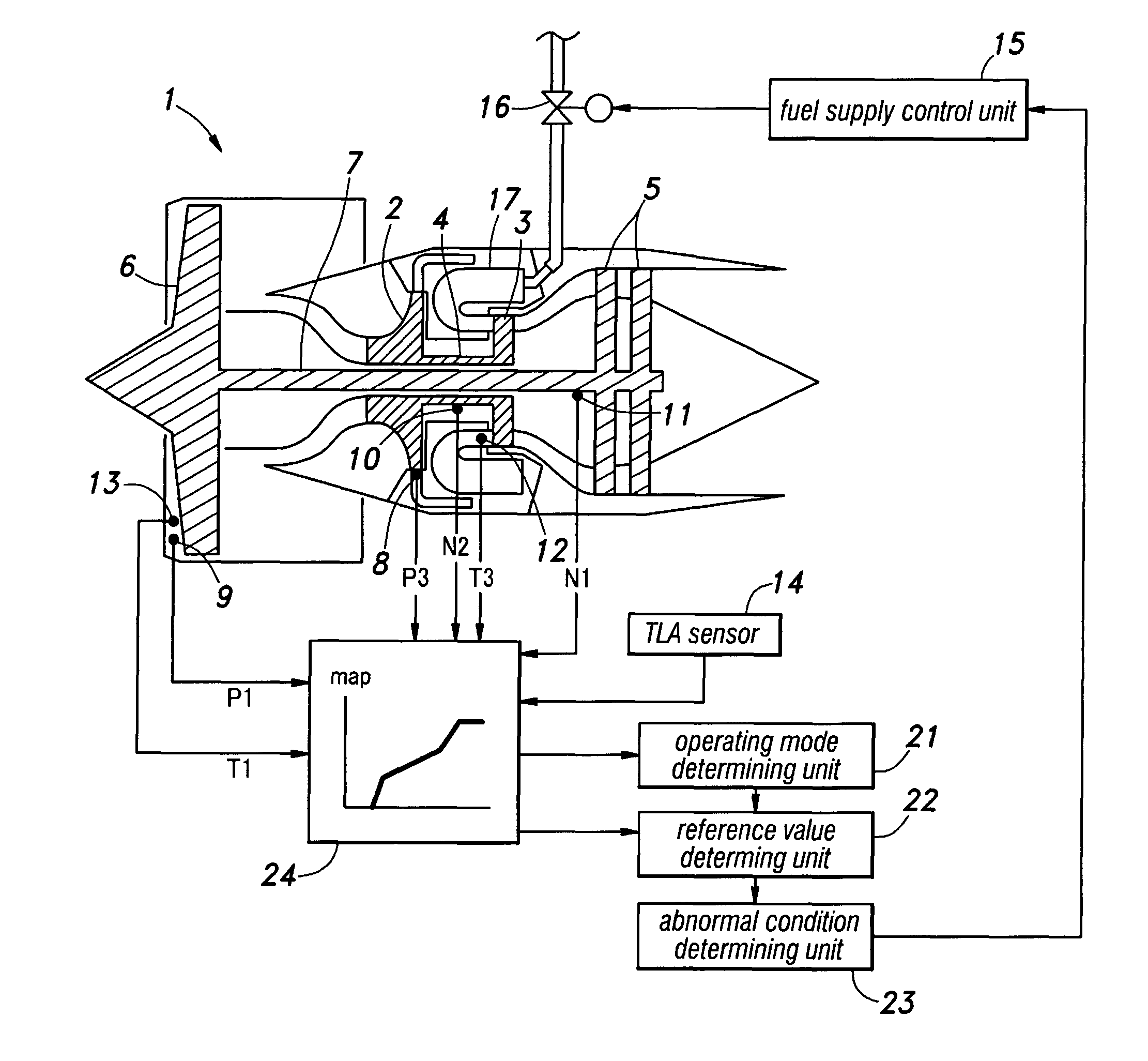
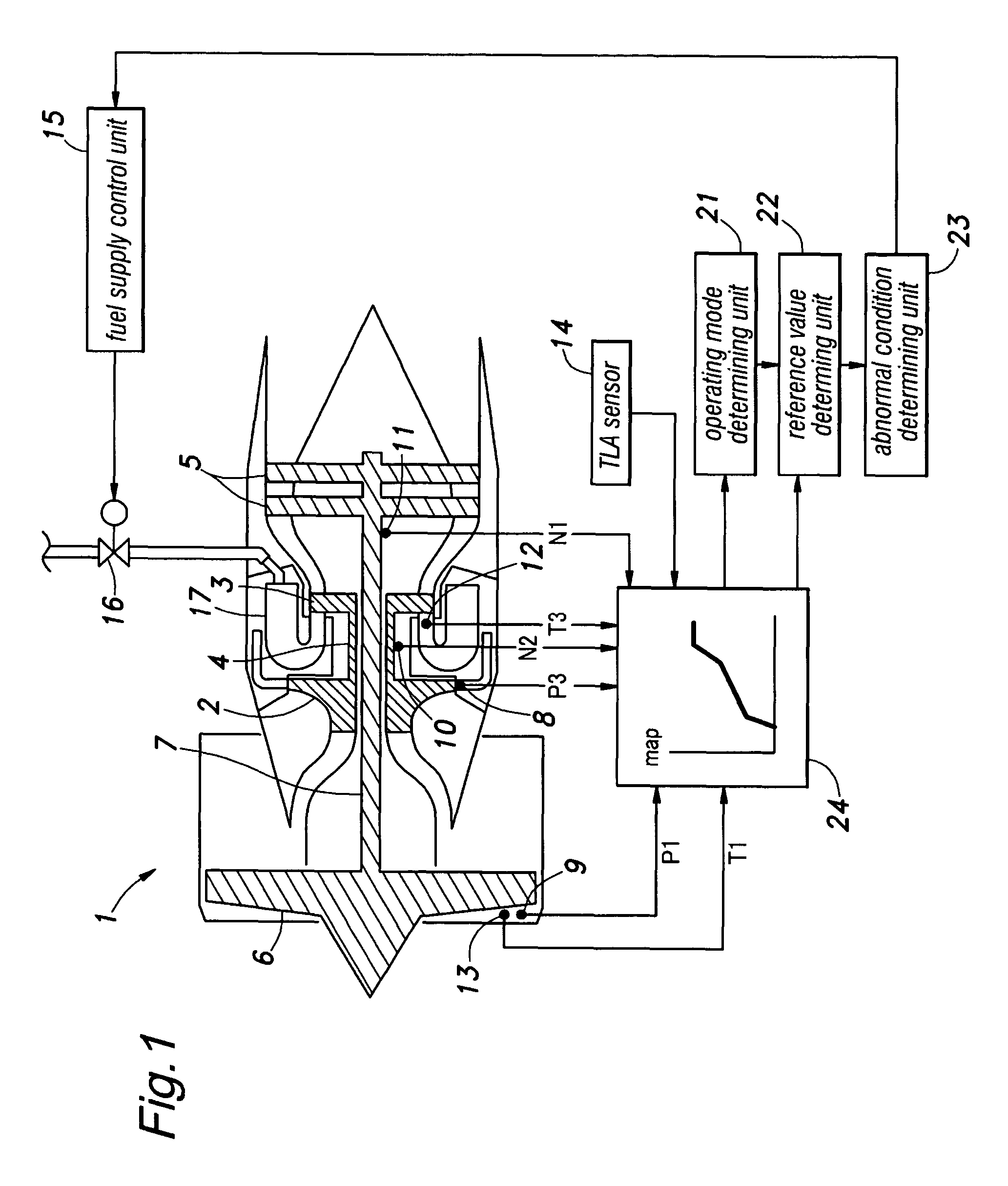
[0024]FIG. 1 schematically illustrates a gas turbine engine to which the present invention is applied. This gas turbine engine 1 comprises a high pressure shaft 4 carrying a compressor rotor 2 and a high pressure turbine wheel 3, and a low pressure shaft 7 carrying a low pressure turbine wheel 5 and a fan 6. A combustion unit 17 is provided immediately upstream of the high pressure turbine. The instrumentation of this engine comprises a high pressure sensor 8 for measuring the outlet pressure P3 of the compressor, a low pressure sensor 9 for measuring the inlet pressure of the fan 6, a high pressure shaft rotational speed sensor 10 for measuring the rotational speed N2 of the high pressure shaft 4, a low pressure shaft rotational speed sensor 11 for measuring the rotational speed N1 of the low pressure shaft 7, a high temperature sensor 12 for measuring the inlet temperature of the high pressure turbine, an inlet air temperature sensor 13 for measuring the temperature of air at the ...


PUM


Abstract

In a system for monitoring an output of a sensor for detecting an operating state of a gas turbine engine by comparing a value of an output of the sensor with a prescribed reference value, a calibration map for converting the output of the sensor into a variable that is normally used for controlling the engine is used for defining the reference value for determining the state of the sensor. Thereby, a fault of a sensor can be detected both accurately and promptly by using the existing resource without unduly complicating the control program. It is particularly desirable to monitor the output of the sensor by taking into account the current operating condition of the engine to improve the reliability in detecting a fault in the sensor.

Description

TECHNICAL FIELD[0001]The present invention relates to a system for monitoring the outputs of sensors that detect various state variables of a gas turbine engine for the purpose of detecting any abnormal condition in any one of the sensors.BACKGROUND OF THE INVENTION[0002]In an aircraft gas turbine engine, a large number of sensors are provided in various parts thereof and the output values of these sensors are used for optimally controlling the operation of the engine. A fault in any one of such sensors may cause abnormal values in the control parameters, and prevents satisfactory operation of the engine. Therefore, it is highly important to take appropriate measures in case of a sensor failure.[0003]A fault of a sensor can be detected in come cases by comparing the output value of the sensor with a certain limit value or the change rate of the output value of the sensor with a prescribed threshold value. See Japanese patent laid-open publication No. 6-264767, for instance.[0004]How...

Claims


Application Information

Patent Timeline
Patent Type & Authority Patents(United States)
IPC IPC(8): G06F19/00G06G7/70
CPCF01D21/003F02C9/28G01D3/022G01D3/08F05D2270/708Y10T477/40F05D2270/304F05D2270/303F05D2270/301F05D2270/094F05D2260/80
Inventor MURAMATSU, HIRONORISUGITANI, YUKINOBU
Owner HONDA MOTOR CO LTD
Why Eureka
Try Eureka