Self-propelled wheel for bicycles and similar vehicles

a self-propelled wheel and bicycle technology, applied in the direction of propulsion by batteries/cells, electric devices, cycles, etc., can solve the problems of time-consuming installation and removal of the propulsion assistor, affecting the operation of the auxiliary motor, and changing the handling characteristics and effective size of the vehicl

Inactive Publication Date: 2010-11-09
RADTKE JEFFREY L
View PDF40 Cites 61 Cited by
  • Summary
  • Abstract
  • Description
  • Claims
  • Application Information

AI Technical Summary

Problems solved by technology

This approach has several disadvantages, e.g., it raises the center of gravity of the vehicle (which can hinder operation), and it is inefficient insofar as propulsion relies on continuously distorting the vehicle's tire.
This approach also carries disadvantages, e.g., it changes the handling characteristics and effective size of the vehicle.
This approach is disadvantageous in that installation and removal of the propulsion assistor is time-consuming: the vehicle is not readily convertible between a solely human-powered vehicle and a propulsion-assisted vehicle.
Given the substantial mass of the battery, this increases the rotational inertia of the wheel, degrading vehicle handling and performance.

Method used


Image

  • Self-propelled wheel for bicycles and similar vehicles
  • Self-propelled wheel for bicycles and similar vehicles
  • Self-propelled wheel for bicycles and similar vehicles

Examples


Embodiment Construction

[0123]To illustrate the invention and the various forms that it may take, following is a description of several exemplary versions of the invention, which will be described with reference to the accompanying drawings.

First Exemplary Version of the Invention (FIGS. 1-10)

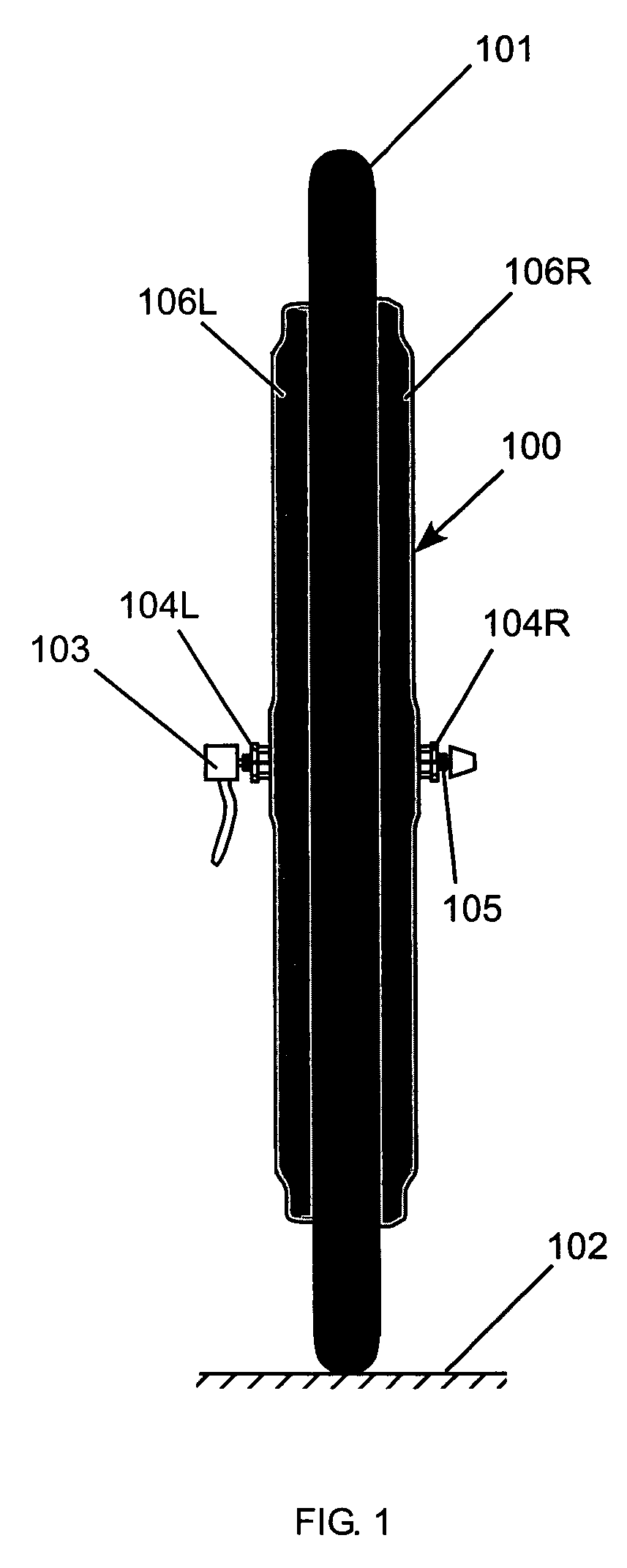
[0124]FIG. 1 shows an end view of a wheel 100 specifically configured for use with a bicycle. The wheel 100 includes a tire 101, which contacts the pavement 102 during normal use. The tire 101 may be a standard 26xl.5 inch tire in this version. The wheel preferably attaches to the bicycle with a quick release assembly 103, such as is found on many bicycles currently sold. The quick release assembly 103 functions in the usual way, such that compression between the quick release assembly 103 and a left bearing cone locknut 104L and a right bearing cone locknut 104R rigidly attaches the wheel 100 to a standard bicycle, with an axle 105 fitting into a bicycle fork dropout. A left external support member 106L and a right e...


PUM


Abstract

A wheel with a self-contained drive mechanism is provided to propel (or assist in propulsion of) bicycles, tricycles, and similar vehicles. The wheel preferably takes the form of a detachable wheel which is readily received within the dropouts of a bicycle frame or fork to be attached therein by a standard quick-release mechanism. Thus, the wheel may be added to (or removed from) preexisting standard bicycles and the like.

Description

CROSS-REFERENCE TO RELATED APPLICATIONS[0001]This application is a continuation-in-part of the following International (PCT) Patent Application:[0002]PCT / US03 / 35807 filed Nov. 12, 2003which itself claims the benefit of priority of the following U.S. Provisional Patent Applications:[0003]60 / 452,775 filed Mar. 8, 2003; and[0004]60 / 430,554 filed Dec. 3, 2002.[0005]This application additionally claims the benefit of priority under 35 USC §119(e) of the following U.S. Provisional Patent Applications:[0006]60 / 603,629 filed Aug. 24, 2004;[0007]60 / 583,461 filed Jun. 28, 2004;[0008]60 / 571,291 filed May 15, 2004;[0009]60 / 563,735 filed Apr. 20, 2004;[0010]60 / 554,936 filed Mar. 20, 2004;[0011]60 / 541,456 filed Feb. 3, 2004; and[0012]60 / 525,951 filed Nov. 28, 2003.The entireties of all of the foregoing applications are incorporated by reference herein.FIELD OF THE INVENTION[0013]This document concerns an invention relating generally to devices for assisting in the propulsion of human-powered vehi...

Claims


Application Information

Patent Timeline
Patent Type & Authority Patents(United States)
IPC IPC(8): B62M7/12B62M6/40B62M6/45B62M6/60B62M6/75B62M6/90
CPCB62M6/45B62M6/75B62M6/90B60L3/0061B60L11/007B60L11/1803B60L11/1877B60L15/2063B62M6/60Y02T10/642B60L2200/12B60L2220/44B60L2240/12B60L2240/14B60L2240/36B60L2240/421B60L2240/423B60L2240/425B60L2240/545B60L2250/24B60L2260/22B60L2200/26Y02T10/7005Y02T10/705Y02T10/7275B60L50/20B60L50/51B60L50/66Y02T10/64Y02T10/70Y02T10/72
Inventor RADTKE, JEFFREY L.NOELDNER, HANS T.
Owner RADTKE JEFFREY L
Why Eureka
Try Eureka