Quick-release support strap device

a support strap and quick-release technology, applied in the field of support straps, can solve the problems of difficult to quickly and easily remove the rifle or shotgun from the gun rest and use, and the hunter's tiringness, so as to reduce the weight of the bag, reduce the amount of energy reserved, and prevent fraying and tangling. the effect of the cord

Inactive Publication Date: 2010-11-09
SLESAR JEFF
View PDF20 Cites 27 Cited by
  • Summary
  • Abstract
  • Description
  • Claims
  • Application Information

AI Technical Summary

Benefits of technology

[0013]The present invention provides a quick-release support strap device which includes a longitudinally extended support strap having a first generally elastic section having a strap connection end and a second mounting clip connection section having a mounting clip connection end opposite the connection end. A releasable strap securement device such as a clip or other such device is mounted on the first generally elastic section adjacent the strap connection end for releasably connecting the support strap to a securement object, and a mounting clip is mounted on the second mounting clip connection section generally adjacent the mounting clip connection end, the mounting clip including a clip body, a clip arm pivotably mounted on the clip body and a releasable latch mounted on the clip body operative to releasably retain at least a portion of the clip arm therein to alternately secure and release the clip arm to open and close the mounting clip. A generally flexible tensioning member such as a cord includes a first end operatively connected to the releasable latch on the mounting clip and an outer end, the generally flexible tensioning member operative to disengage the releasable latch to release the portion of the clip arm therefrom to release the clip arm and open the mounting clip. The generally flexible tensioning member is at least partially slidably housed within the second mounting clip connection section of the support strap such that the outer end of the generally flexible tensioning member is engagable to tension the generally flexible tensioning member to slide within the support strap and disengage the latch. Finally, the mounting clip is operative to releasably engage an object suspended on a wearer's shoulder and the longitudinally extended support strap is operative to extend around the neck portion of a wearer of the longitudinally extended support strap and be releasably secured via the releasable strap securement means on the wearer below the neck portion thereof such that the object is generally prevented from dislodging from the wearer's shoulder.
[0014]The present invention as thus described provides many advantages over those devices or methods found in the prior art. For example, because the latch of the quick-release support strap device of the present invention is disengaged by the free hand of the user, the gun supporting hand is free to quickly move the gun into a firing position while the free hand of the gun user can then move to support the gun in the firing position. Also, because the weight of the gun is supported by the support strap during non-use of the gun, the user of the present invention will not use valuable energy supporting the gun while he or she is walking around the hunting area, thus leaving greater energy reserved available when needed by the hunter. Furthermore, because the cord of the present invention extends within the support strap, fraying and tangling of the cord is generally prevented which provides added insurance for the proper functioning of the quick-release support strap device of the present invention when release of the gun is needed. Finally, and perhaps most importantly, the quick-release support strap device of the present invention is usable not only with rifles and shotguns, but with many different types of bags, backpacks, knapsacks, or other such carrying devices, as the clip will engage the shoulder strap of the carrying device and support the weight of the device around the neck and back of the wearer instead of directly on the shoulder of the wearer. It has been found that this redistribution of the weight of the bag is beneficial and such additional use of the quick-release support strap device of the present invention is not found in the prior art. It is therefore seen that the present invention provides a substantial improvement over those devices and methods found in the prior art.

Problems solved by technology

Needless to say, this can grow quite tiring for the hunter, particularly in the shoulder, arms, and back areas of the hunter which provide the majority of support for the weight of the rifle or shotgun.
The natures of these devices, however, render it quite difficult to quickly and easily remove the rifle or shotgun from the gun rest and use it as is necessary when the game animal is flushed from its place of hiding and the hunter must quickly respond to the event.

Method used


Image

  • Quick-release support strap device
  • Quick-release support strap device
  • Quick-release support strap device

Examples


Embodiment Construction

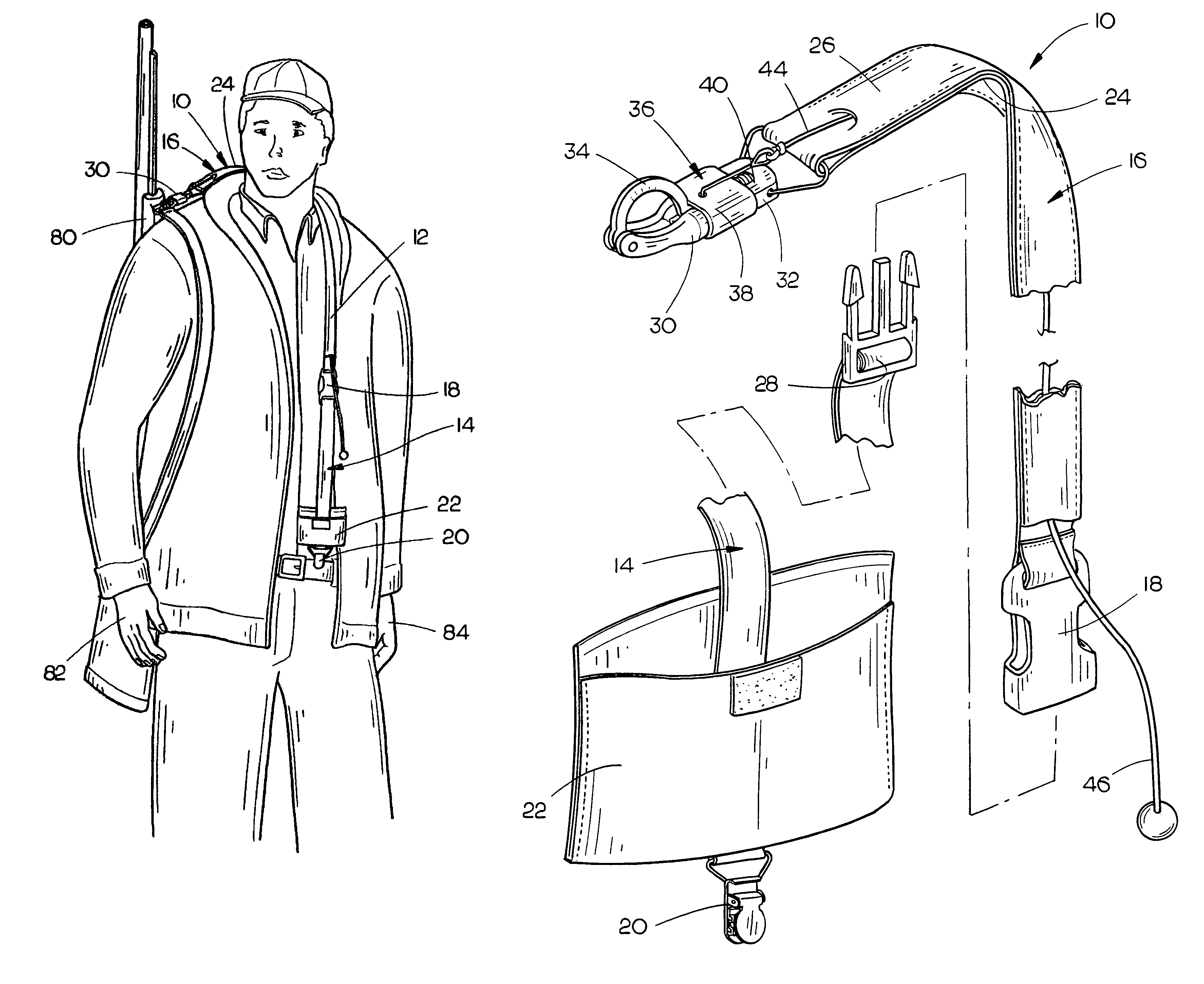
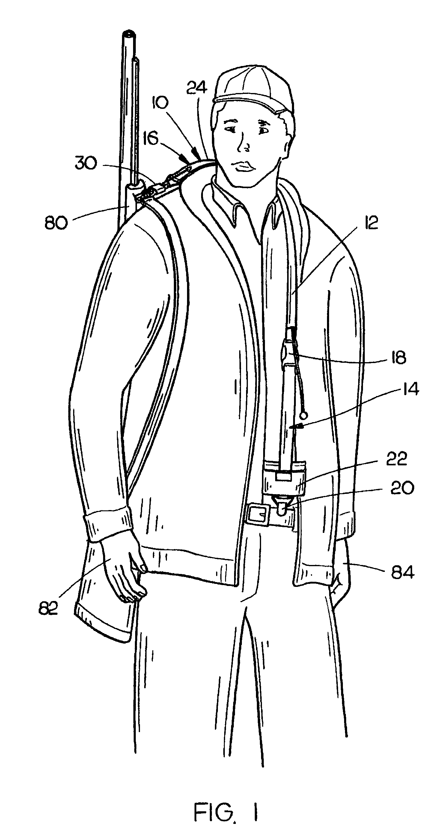
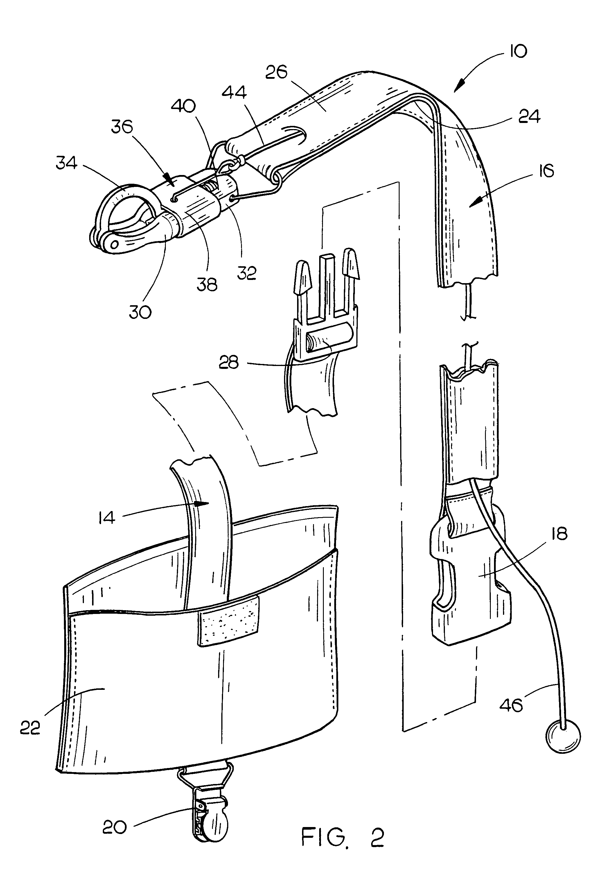
[0020]The quick-release support strap device 10 of the present invention is shown best in FIGS. 1-3 as including a longitudinally extended support strap 12 having a first generally elastic section 14 and a second mounting clip connection section 16. The first elastic section 14 and second mounting clip connection section 16 would preferably be connected to one another by an intermediate strap clip 18, as shown best in FIGS. 1 and 2, although it may be preferable to construct the support strap 12 as a unitary piece should such a design change prove beneficial. However, it has been found that constructing the support strap 12 as shown in FIGS. 1 and 2 renders the quick-release support strap device 10 of the present invention easier to use and also easier to assemble.

[0021]In the preferred embodiment, first elastic section 14 of support strap 12 would have a length of approximately six to eighteen inches when untensioned and would be constructed of any of a number of different types of...


PUM


Abstract

A quick-release support strap device includes a longitudinally extended support strap having a first generally elastic section and a second mounting clip connection section. A releasable strap securement device such as a clip is mounted on the first generally elastic section for releasably connecting the support strap to a securement object, and a mounting clip is mounted on the second mounting clip connection section including a clip body, a clip arm pivotably mounted on the clip body and a releasable latch mounted on the clip body operative to releasably retain at least a portion of the clip arm therein. A cord is housed at least partially within the support strap and is operatively connected to the releasable latch on the mounting clip, the cord operative to disengage the releasable latch to release the portion of the clip arm therefrom to release the clip arm and open the mounting clip.

Description

BACKGROUND OF THE INVENTION[0001]1. Technical Field[0002]The present invention relates to support straps for objects and, more particularly, to a quick-release support strap device which includes a longitudinally extended support strap having a first generally elastic section and a second mounting clip connection section, a mounting clip mounted on the mounting clip connection section which includes a latch, a releasable strap securement device for connecting the support strap to a securement object and a generally flexible tensioning member such as a cord which is connected to and extends from the latch on the mounting clip through the body of the support strap to a position intermediate the opposite ends of the support strap such that the mounting clip may be connected to a device for support thereof with the strap extending over and around the neck of the individual wearing the device for connection to the pants or belt of the person such that the object being supported may be qu...

Claims


Application Information

Patent Timeline
Patent Type & Authority Patents(United States)
IPC IPC(8): A45F3/02A45F3/14A01K1/08A45C13/30A45C1/04
CPCA45F5/02F41C23/02F41C33/002A45F5/021A45F2005/006A45F2200/0591
Inventor SLESAR, JEFF
Owner SLESAR JEFF
Why Eureka
Try Eureka