Electric socket having means to lock the blades of inserted electric plug

a technology of electric sockets and blades, which is applied in the direction of coupling device details, coupling device connections, two-pole connections, etc., can solve the problems of inconvenient operation of this design, affecting the force applied to plug/unplug the electric plug, and temperature rise, so as to achieve convenient operation and high level of safety

Active Publication Date: 2010-11-09
TA HSING ELECTRIC WIRE & CABLE
View PDF7 Cites 9 Cited by
  • Summary
  • Abstract
  • Description
  • Claims
  • Application Information

AI Technical Summary

Benefits of technology

[0008]The present invention has been accomplished under the circumstances in view. It is one object of the present invention to p

Problems solved by technology

This contact manner produces a high contact resistance, resulting in a temperature rise.
However, the operation of this design is inconvenient.
However, using the screw-style plunger to force the prongs affects the application of force to plug/unplug the electric plug.
In consequence

Method used


Image

  • Electric socket having means to lock the blades of inserted electric plug
  • Electric socket having means to lock the blades of inserted electric plug
  • Electric socket having means to lock the blades of inserted electric plug

Examples


Embodiment Construction

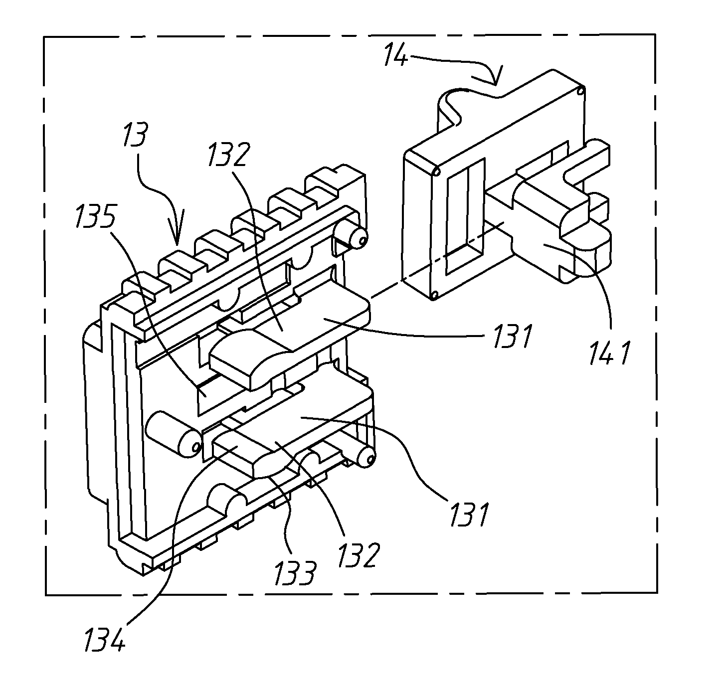
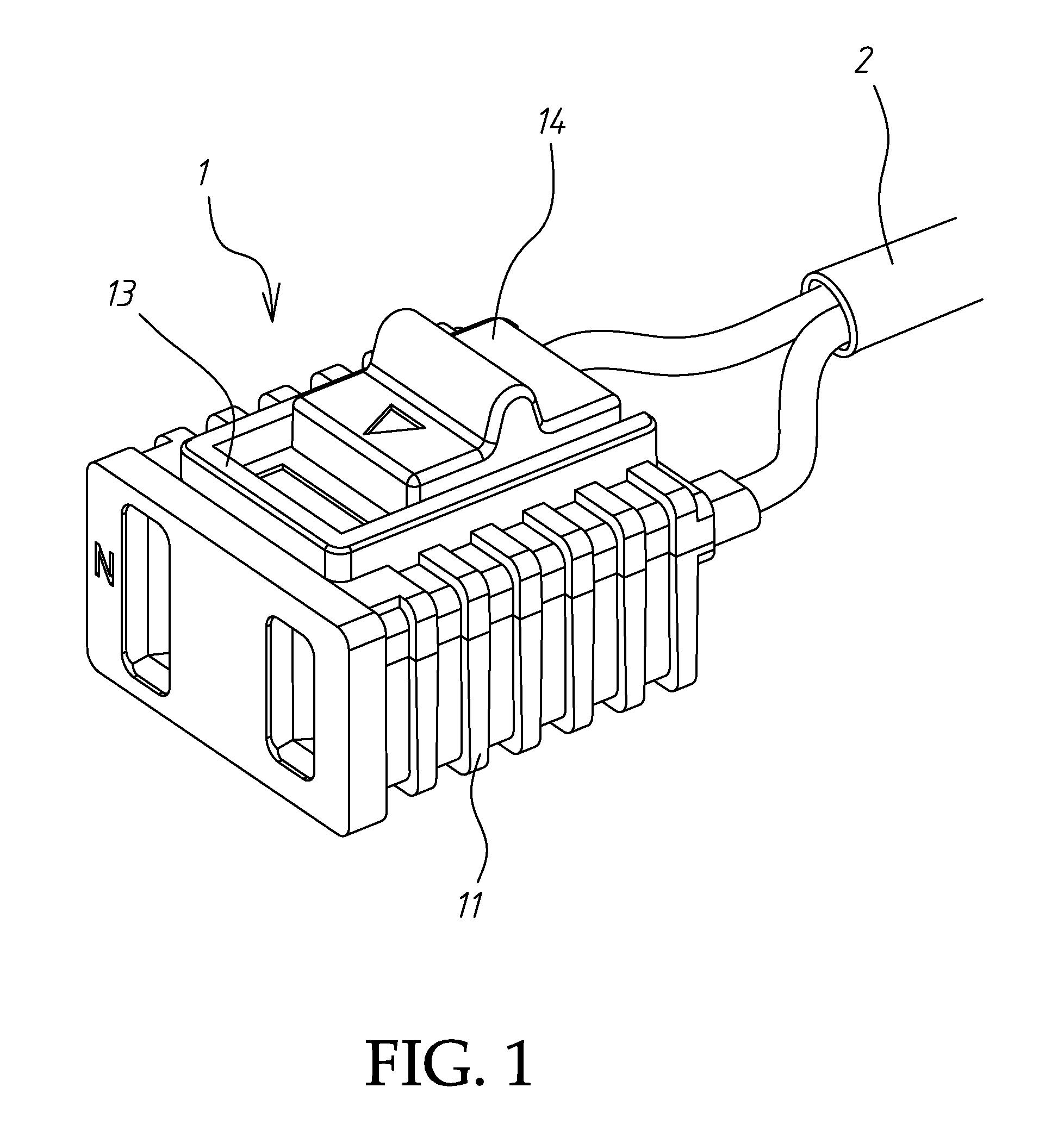
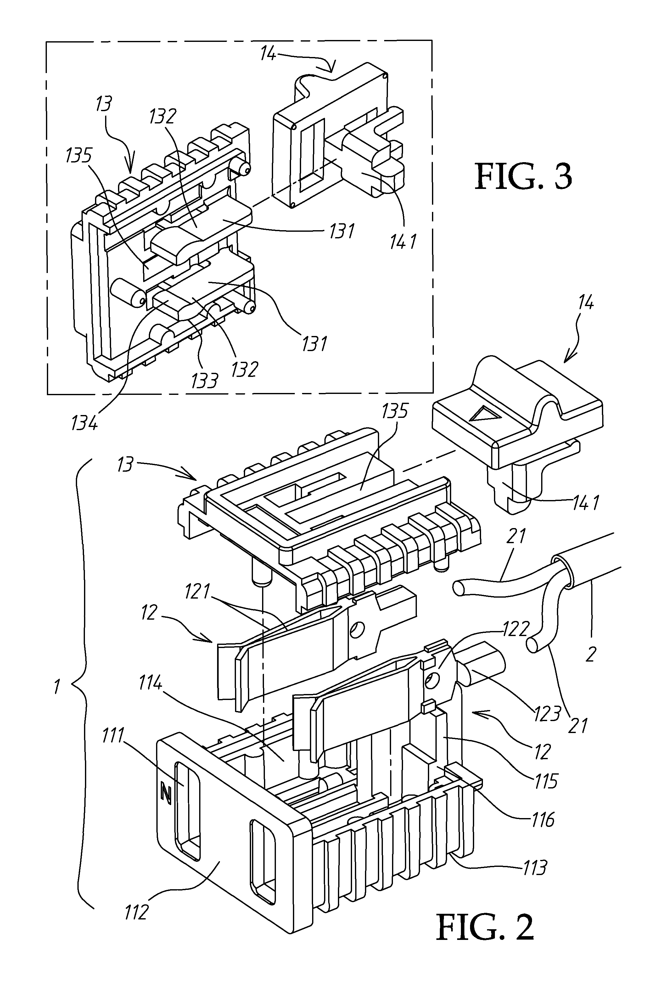
[0026]Referring to FIGS. 1 and 2, an electric socket 1 in accordance with the present invention is shown connected to positive pole and negative pole conductors 21 of a power cord 2 for the connection of the metal conducting blades 31 of an electric plug 3 (see also FIG. 7 or FIG. 9) electrically. The electric socket 1 comprises an electrically insulative bottom shell 11, two metal electrode clamps 12, an electrically insulative top shell 13 and a sliding block 14.

[0027]The electrically insulative bottom shell 11 has a front wall 112, a rear wall 115 opposite to the front wall 112, two insertion slots 111 cut through the front wall 112 for the insertion of the two metal conducting blades 31 of the electric plug 3 respectively, two sidewalls 113 bilaterally connected between the front wall 112 and the rear wall 115, a bottom wall (not shown), an accommodation chamber 114 surrounded by the front wall 112, the rear wall 115, the bottom wall and the two side walls 113, and two rear notc...


PUM


Abstract

An electric socket includes an electrically insulative bottom shell, two metal electrode clamps mounted inside the electrically insulative bottom shell, an electrically insulative top shell covering the electrically insulative bottom shell and having two bottom spacer ribs set between the two metal electrode clamps to keep them apart, and a sliding block slidably coupled to the electrically insulative top shell and movable between a locking position where a bottom protruding block of the sliding block pushes the free end of each spacer rib sideways against the front clamping strips of the metal electrode clamps, thereby causing the metal electrode clamps to be locked to the metal conducting blades of the inserted electric plug and an unlocking position where the bottom protruding block of the sliding block is released from the spacer ribs, thereby unlocking the meal electrode clamps from the metal conducting blades of the inserted electric plug.

Description

BACKGROUND OF THE INVENTION[0001]1. Field of the Invention[0002]The present invention relates to electric sockets and more particularly, to an electric socket having means to lock the blades of inserted electric plug.[0003]2. Description of the Related Art[0004]An electric socket is an important electric connector for the insertion of an electric plug to obtain power supply. Many electric socket patents have been issued. Taiwan Utility Patent No. M261875, issued on Apr. 11, 2005, discloses an electric socket, entitled “Electric Socket Locking Structure”, which comprises a housing 1, a socket body 2 and a locking device 3. By means of rotating the knob 31 of the locking device 3 to press the protruding portions 314 of the knob 31 on top blocks 323 of a holding down member 32, protruding blocks 332 of a retaining member 33 that is rotated by the knob 31 are respectively moved over the protruding blocks 324 of the holding down member 32 into a respective groove 322 on the bottom wall o...

Claims


Application Information

Patent Timeline
IPC IPC(8): H01R11/22
CPCH01R13/639H01R24/28H01R2103/00
Inventor LIU, WEI-HO
Owner TA HSING ELECTRIC WIRE & CABLE
Why Eureka
Try Eureka