
Input device and an electronic device comprising an input device

a technology of input device and electronic device, which is applied in the direction of electronic switching, basic electric elements, pulse techniques, etc., can solve the problems of unintentional or accidental key presses, unintentional and unintentional key presses of certain key combinations, and inability to perform a single quick operation. , to prevent inadvertent input, operate faster to perform a single quick operation, and prevent inadvertent input

Inactive Publication Date: 2010-11-09
SONY CORP
View PDF33 Cites 46 Cited by
  • Summary
  • Abstract
  • Description
  • Claims
  • Application Information

AI Technical Summary

Benefits of technology

The solution effectively prevents accidental key presses by ensuring that only a user's intentional touch activates the input, reducing unwanted device operations and enhancing the locking mechanism's reliability when the device is in a bag or pocket.

Problems solved by technology

The above examples of operations may be cumbersome and annoying to some users.
While the known prior art mobile terminals may provide acceptable locking mechanisms in most cases, there is still a risk that accidental and unintentional key presses occur if the device is in a bag / pocket / purse.
When these objects lie against the device, they may sometimes press the buttons of the keypad of the device by accident.
If the device uses a certain key combination for unlocking the key-lock function this certain key combination could in fact be unintentionally or accidentally pressed by the objects lying against the device.
There is consequently a risk that the key-lock function would be unintentionally unlocked if objects press the certain key combination by accident.
This may lead to the keypad being left unlocked, this in turn potentially leading to accidental phone calls or the like.
While the timer lock solves this problem partly, there is still the timeout period when random key-presses can initiate unintentional phone calls or interfere with the operation of the device otherwise, e.g., by entering notes into the calendar or by entering names into the phonebook.

Method used


Image

  • Input device and an electronic device comprising an input device
  • Input device and an electronic device comprising an input device
  • Input device and an electronic device comprising an input device

Examples


first embodiment

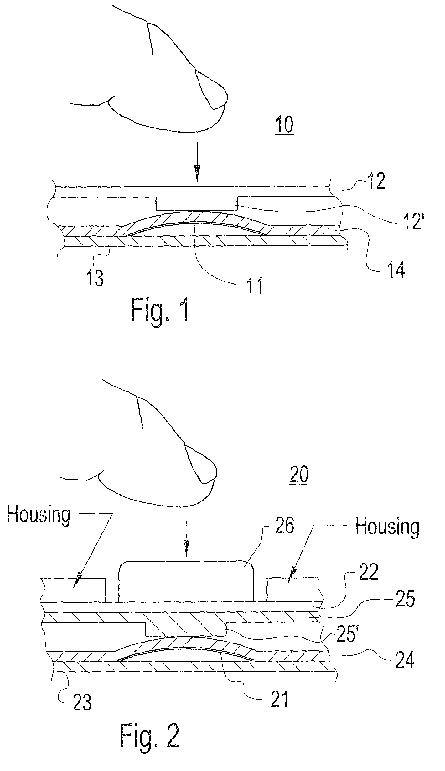
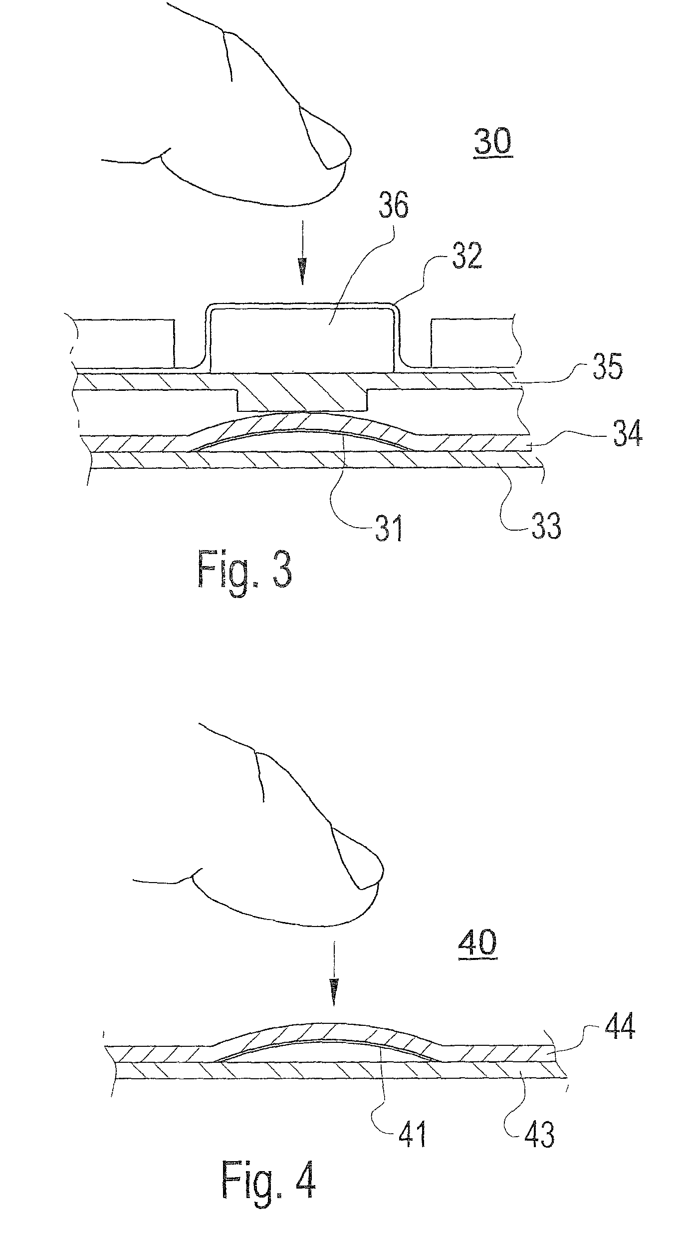
[0067]FIG. 1 illustrates an input device 10 according to the invention. The input device 10 is operatively connected to electronic circuits (not shown) in the electronic device, in which the input device 10 is implemented. A switch device in the form of a switch dome 11 is mounted on a support structure 13, such as a Printed Circuit Board (PCB) or the like. The PCB may be a rigid PCB or a flexible printed circuit (FPC). In this example, the switch dome 11 is configured to provide tactile feedback for a user when the user pushes or presses the switch dome 11 with his finger. In the embodiment shown in FIG. 1, the switch dome 11 is a metal dome switch. The metal dome switch may be covered by a dome cover layer 14. The dome cover layer 14 may be made of any flexible material such as, e.g., plastic, rubber, Polyethylene terephthalate (PET), etc. However, it should be appreciated that the switch dome 11 could equally possibly be a plastic switch dome. If the switch dome 11 is a plastic s...

second embodiment

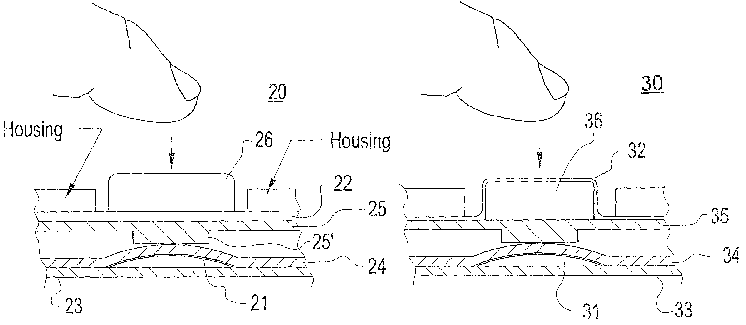
[0071]FIG. 2 illustrates an input device 20 according to the invention. The input device 20 is operatively connected to electronic circuits (not shown) in the electronic device, in which the input device 20 is employed. A switch dome 21 is mounted on a support structure 23, such as a Printed Circuit Board (PCB) or the like. The PCB may be a rigid PCB or a flexible printed circuit (FPC). Like the previous embodiment, the switch dome 21 may suitably be configured to provide tactile feedback for a user when the user pushes or presses towards the switch dome 21 with a finger. The switch dome 21 may be a metal dome switch. The metal dome switch may be covered by a dome cover layer 24. The dome cover layer 14 may be made of plastics. The input device 20 also comprises a capacitive touch sensing device in the form of a capacitive touch screen. In this embodiment, the capacitive touch screen comprises a flexible substrate 22 onto which a conductive layer is coated. Furthermore, the flexible...

third embodiment

[0076]FIG. 3 illustrates an input device 30 according to the invention. The input device 30 is operatively connected to electronic circuits (not shown) in the electronic device, in which the input device 30 is employed. A switch dome 31 is mounted on a support structure 33, such as a Printed Circuit Board (PCB) or the like. The PCB may be a rigid PCB or a FPC. The switch dome 31 may be configured to provide tactile feedback for a user when the user pushes or presses towards the switch dome 31 with his finger. The switch dome 31 may be a metal dome switch. The metal dome switch may be covered by a dome cover layer 34. The dome cover layer 34 may be made of plastics. The input device further comprises a key or button 36. The input device 30 is also provided with a capacitive touch screen 32. More particularly, the button 36 is coated with a thin conductive layer 32 for forming the capacitive touchpad. The button is attached onto a substrate 35, e.g. thin and flexible key mat substrate...


PUM


Abstract

An input device including a support structure, such as a Printed Circuit Board (PCB), and a switch device, e.g. a switch dome, mounted on the support structure. The switch device may be configured to provide tactile feedback to a user upon depression of the switch device by a finger of the user. The input device also comprises a capacitive touch sensing device, e.g. a capacitive touch screen, which is positioned in relation to the switch device such that the capacitive touch sensing device is configured to sense the capacitance of the finger upon depression of the switch device by the finger. The invention also concerns an electronic device, e.g. a mobile phone, comprising one or several input devices.

Description

CROSS REFERENCE TO RELATED APPLICATION[0001]This application claims priority under 35 U.S.C. §119 to U.S. Provisional Application No. 60 / 947,710, filed Jul. 3, 2007, the entire disclosure of which is incorporated herein by reference.TECHNICAL FIELD[0002]The present invention relates in general to an input device for inputting information to an electronic device. The present invention also relates to electronic devices, such as mobile terminals, e.g., mobile telephones, personal digital assistants (PDAs), digital camera devices and / or handheld computers, including one or several such input devices.BACKGROUND[0003]A variety of portable electronic devices, such as mobile terminals (e.g., mobile telephones, PDA:s, media players and / or handheld computers), are widely used today. In many of these electronic devices, the keypad can be locked when the portable electronic device is not used. There are many different ways to implement the keypad lock feature. Some mobile terminals use a seque...

Claims


Application Information

Patent Timeline
Patent Type & Authority Patents(United States)
IPC IPC(8): H03K17/975
CPCH01H13/702H03K17/962H01H2003/0293H01H2215/004H01H2231/022H01H2239/006H03K2217/96054H03K2217/960755H03K2217/96062
Inventor TOLBERT, WILLIAM HAYWOODSTEIJNER, JOHAN MAGNUS RIKARD
Owner SONY CORP
Learn More