Isolated high power bi-directional DC-DC converter

a converter and high-power technology, applied in the field of electric power conversion systems, can solve the problems of reducing reliability, multiple units, and increasing the overall system cos

Inactive Publication Date: 2010-11-09
HONEYWELL INT INC
View PDF9 Cites 32 Cited by
  • Summary
  • Abstract
  • Description
  • Claims
  • Application Information

AI Technical Summary

Problems solved by technology

There are a number of drawbacks with using multiple power conversion systems.
The multiple units may add to the overall system cost.
Also, the additional electrical components can reduce reliability and lower efficiency.
Prior bi-directional dc-dc converters can suffer from one or more of the following problems: high switching losses, necessity of an isolated feedback, difficult no-load control, and low efficiency due to losses in the output rectifier, particularly with low output voltages.

Method used


Image

  • Isolated high power bi-directional DC-DC converter
  • Isolated high power bi-directional DC-DC converter
  • Isolated high power bi-directional DC-DC converter

Examples


Embodiment Construction

[0023]The following detailed description is of the best currently contemplated modes of carrying out the invention. The description is not to be taken in a limiting sense, but is made merely for the purpose of illustrating the general principles of the invention, since the scope of the invention is best defined by the appended claims.

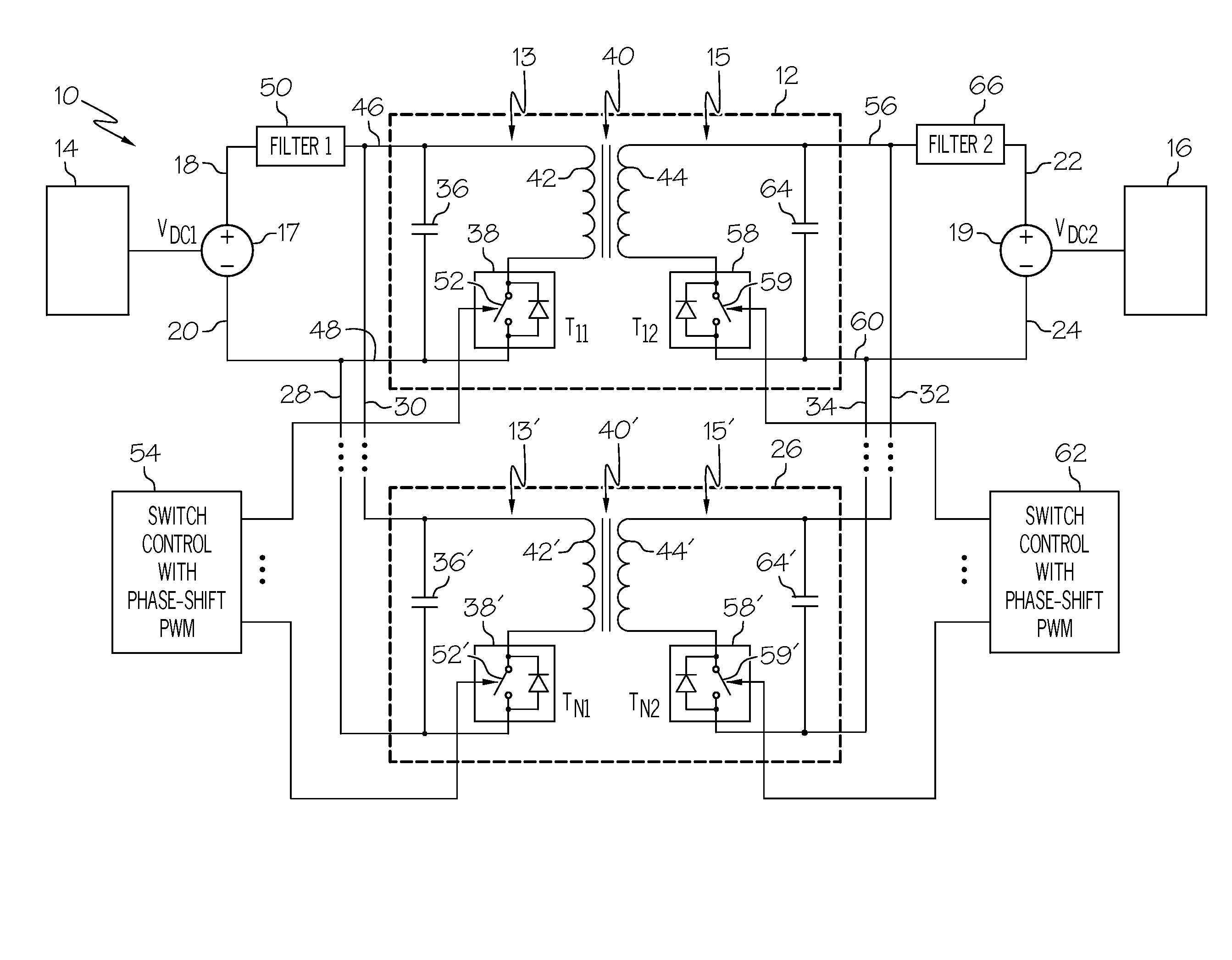
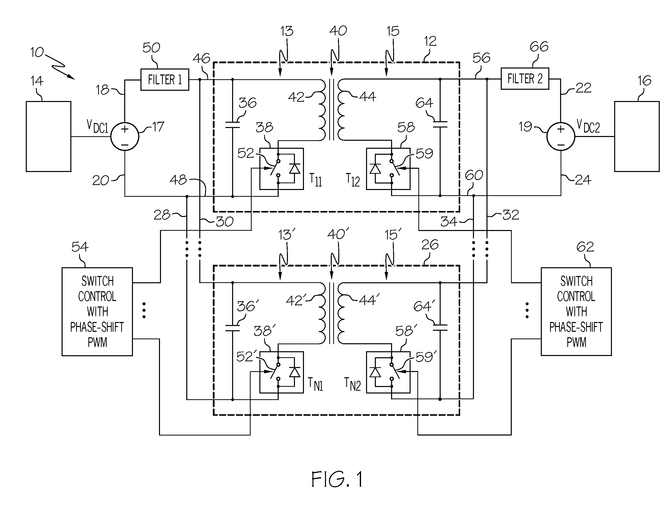
[0024]The present invention generally provides a bi-directional dc-dc converter that may provide power conversion for two separate electrical power systems on board an aircraft. The two electrical power systems may have different functions, electrical requirements and power transfer directions. The bi-directional dc-dc converter may include back-to-back dc-dc converter circuits isolated from each other by a transformer that can operate bi-directionally. N number of such dc-dc converters may be connected in parallel to increase power capability. Phase shift pulse width modulation (PWM) may be used to switch the parallel dc-dc converters so as to decrease...


PUM


Abstract

A bi-directional dc-dc converter is provided that may provide voltage conversion for two separate electrical power systems. The two electrical power systems may have different functions, electrical requirements and power transfer directions. The bi-directional dc-dc converter may include back-to-back bi-directional dc-dc converter circuits isolated from each other by a transformer. Multiple such dc-dc converters may be connected in parallel to increase power capability. Phase shift pulse width modulation (PWM) may be used to switch the parallel dc-dc converters so as to decrease both voltage ripple and current ripple. The number of dc-dc converters may be modified to meet the different needs of various electric power systems. A single bi-directional dc-dc converter of the invention may be employed to provide electric power conversion for multiple electric power systems, even where those systems have different power requirements and different power transfer directions.

Description

BACKGROUND OF THE INVENTION[0001]The present invention relates to electric power conversion systems, and more particularly, to switched mode energy storage DC-DC electric power conversion systems capable of providing power to a plurality of electric power systems.[0002]Electric power systems, such as those found on vehicles and aircraft, often are used to produce electric power for different kinds of on-board electronic equipment having different functions and electrical requirements. For example, battery chargers and motors, such as those used for starters in auxiliary power units, may require different voltages, currents and polarities.[0003]Electric power conversion systems are used to supply subsystems with the required electrical energy by converting electrical energy from a main generator into the specific form needed. Where electrical subsystems have very different functions and power transfer directions, such as starters and motors, more than one electric power conversion sy...

Claims


Application Information

Patent Timeline
Patent Type & Authority Patents(United States)
IPC IPC(8): H02M7/00
CPCH02M3/285H02M3/33584H02M1/0043
Inventor ZENG, QINGRONGSINGH, TEJINDERMORCOV, NICOLAE A.
Owner HONEYWELL INT INC
Why Eureka
Try Eureka