
Damping element for a fuel injection valve

a technology of adamant element and a fuel injection valve, which is applied in the direction of fuel injection apparatus, noise reduction fuel injection, charge feed system, etc., can solve the problems of a large axial installation space and comparatively high manufacturing cost of the adamant element, and achieve good solid-borne sound damping and better sound-damping

Inactive Publication Date: 2010-11-16
ROBERT BOSCH GMBH
View PDF25 Cites 20 Cited by
  • Summary
  • Abstract
  • Description
  • Claims
  • Application Information

AI Technical Summary

Benefits of technology

The solution achieves effective solid-borne sound damping with reduced axial installation space and lower manufacturing costs, converting mechanical vibration energy into thermal energy through internal friction, thereby minimizing noise transmission from the fuel injection valve to the cylinder head.

Problems solved by technology

It is disadvantageous that the damping element requires a great deal of axial installation space with respect to a valve axis, and has comparatively high manufacturing costs.

Method used


Image

  • Damping element for a fuel injection valve
  • Damping element for a fuel injection valve
  • Damping element for a fuel injection valve

Examples


Embodiment Construction

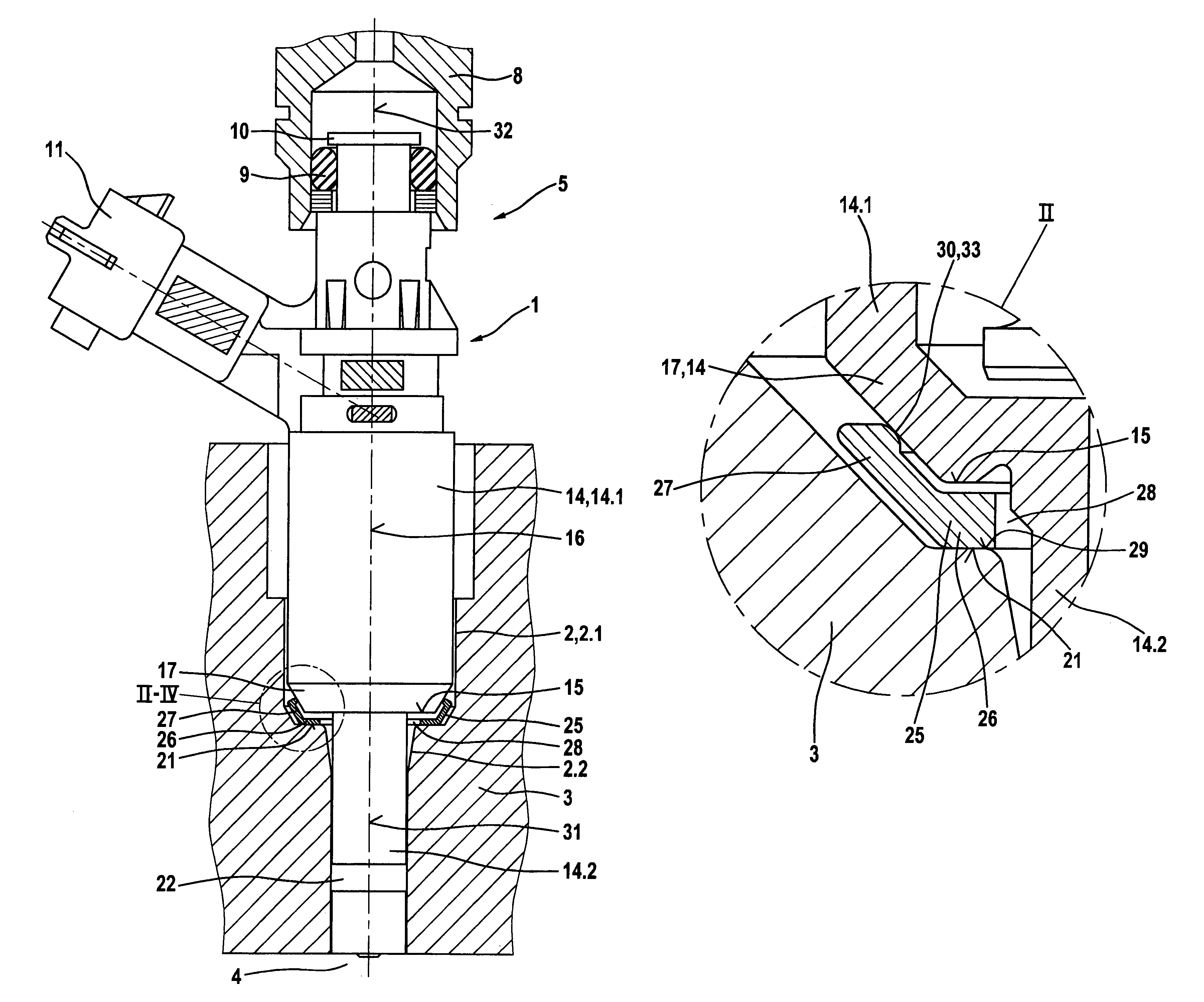
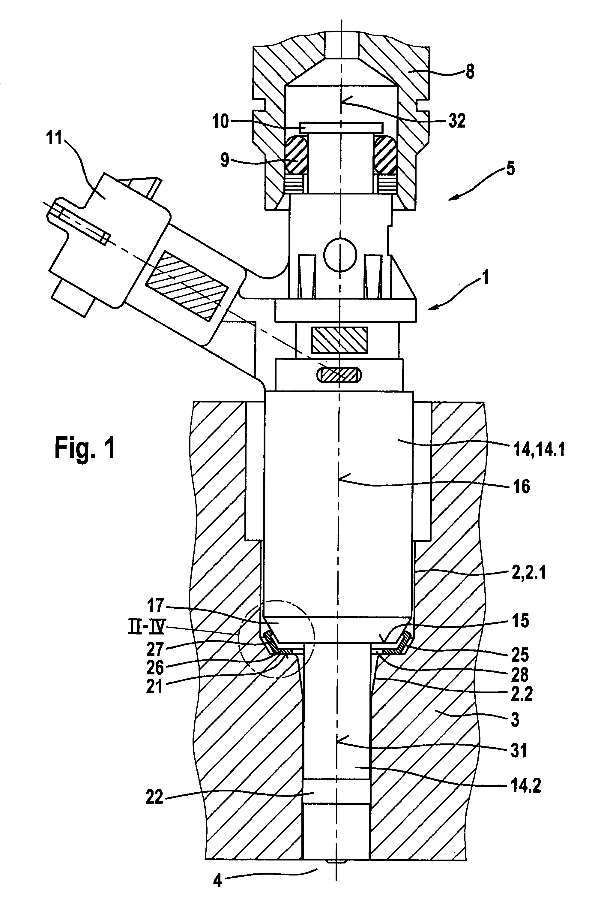
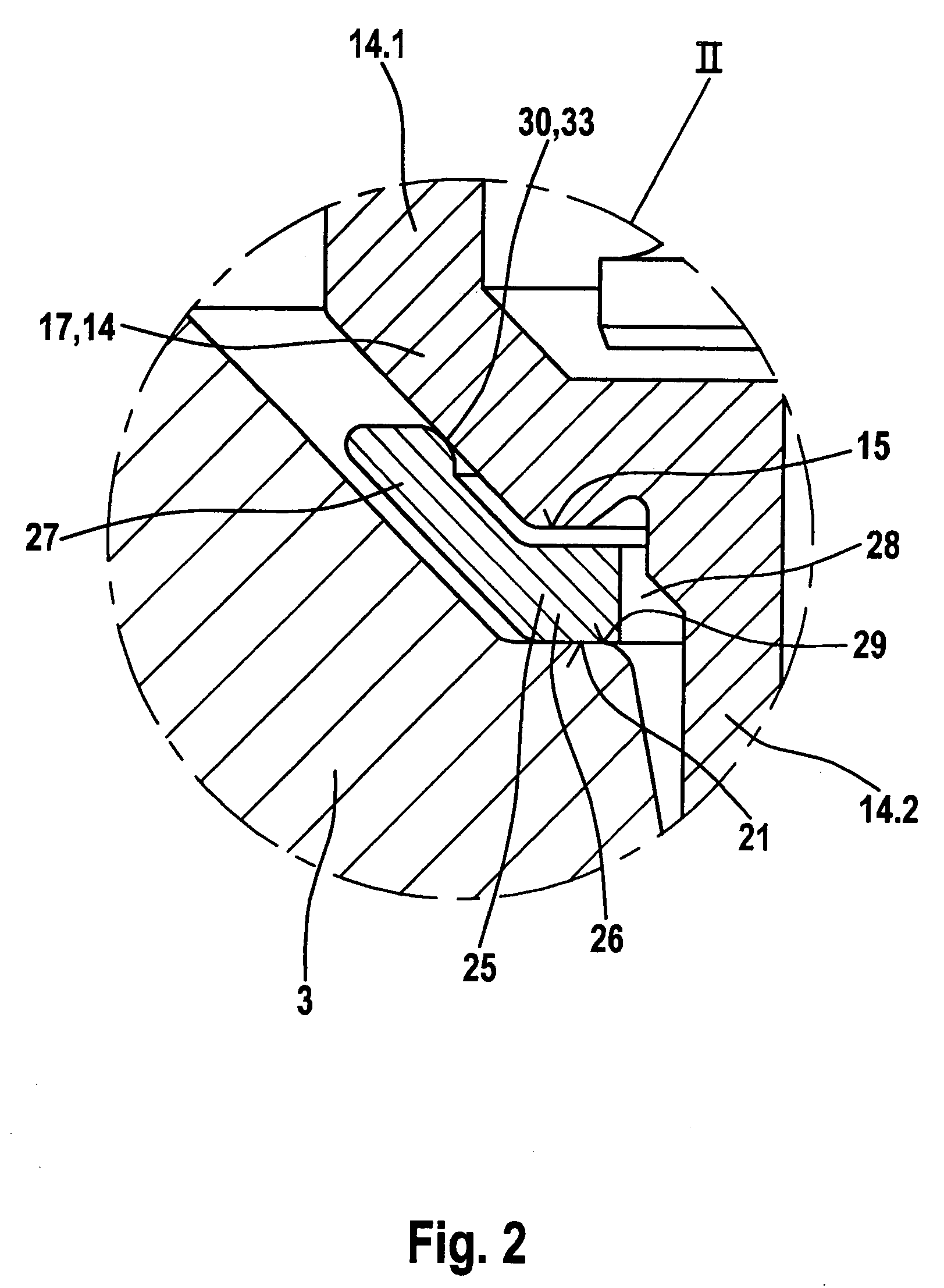
[0015]Several exemplary embodiments of the present invention are depicted in simplified fashion in the drawings and explained further in the description that follows. FIG. 1 shows, in section, a fuel injection valve in a receiving bore of a cylinder head, FIG. 2 illustrates aspects of an exemplary embodiment, FIG. 3 illustrates aspects of an exemplary embodiment, and FIG. 4 illustrates aspects of an exemplary embodiment, in respective details II-IV according to FIG. 1.

[0016]FIG. 1 is a simplified depiction of a fuel injection valve in a receiving bore of a cylinder head, having a damping element according to example embodiments of the present invention between the fuel injection valve and the cylinder head.

[0017]A fuel injection valve 1 is disposed in a receiving conduit 2 of a cylinder head 3 of an internal combustion engine. Fuel injection valve 1 serves to inject fuel into a combustion chamber 4 of the internal combustion engine and is used, for example, in so-called direct injec...


PUM


Abstract

Damping elements for a fuel injection valve insertable into a receiving conduit of a cylinder head of an internal combustion engine are disposed between a valve housing of the fuel injection valve and a wall of the receiving conduit of the cylinder head. These damping elements, inter alia, decrease acoustic transfer from the fuel injection valve to the cylinder head. It is disadvantageous that conventional damping elements require a great deal of axial installation space with respect to a valve axis and have comparatively high manufacturing costs. With the damping element according to example embodiments of the present invention, the installation space required is reduced. Provision is made, according to example embodiments of the present invention, for the damping element to be in plate-shaped fashion.

Description

FIELD OF THE INVENTION[0001]The present invention relates to a damping element for a fuel injection valve.BACKGROUND INFORMATION[0002]A damping element for a fuel injection valve insertable into a receiving conduit of a cylinder head of an internal combustion engine, which element is disposed between a valve housing of the fuel injection valve and a wall of the receiving conduit of the cylinder head, is described in German Published Patent Application No. 100 38 763. The damping element is made up of two rigid rings between which an elastic intermediate ring is disposed. The damping element, inter alia, decreases acoustic transfer from the fuel injection valve to the cylinder head. It is disadvantageous that the damping element requires a great deal of axial installation space with respect to a valve axis, and has comparatively high manufacturing costs.SUMMARY[0003]The damping element according to example embodiments of the present invention, in contrast, may provide that an improve...

Claims


Application Information

Patent Timeline
Patent Type & Authority Patents(United States)
IPC IPC(8): F02M61/14F02M61/18
CPCF02M61/14F02M2200/09F02M2200/30
Inventor MUELLER, MARTINHUEBEL, MICHAEL
Owner ROBERT BOSCH GMBH
Learn More