Apparatus and method for extracting a tubular string from a bore hole

a tubular string and tube technology, applied in the field of well head assembly and wells, can solve the problems of slow and tedious process, difficult to remove drill tubular, and large amount of force to raise the tubular to overcome the resisting for

Inactive Publication Date: 2010-11-16
FANGUY ROBERT P
View PDF16 Cites 17 Cited by
  • Summary
  • Abstract
  • Description
  • Claims
  • Application Information

AI Technical Summary

Problems solved by technology

Removing drill tubular is very difficult because of the tremendous weight of the tubular strings and, in some cases, cement is located around and between the casings.
As discussed above, raising the tubular requires an extensive amount of force to overcome the resisting forces.
The operators usually drill one side at a time, a slow and tedious process, especially with heavy gauge pipe.
Although the time required to drill the holes may be drastically reduced, a significant amount of time is still required to set up, and clear, lubricate and repair the drill bits.

Method used


Image

  • Apparatus and method for extracting a tubular string from a bore hole
  • Apparatus and method for extracting a tubular string from a bore hole
  • Apparatus and method for extracting a tubular string from a bore hole

Examples


Embodiment Construction

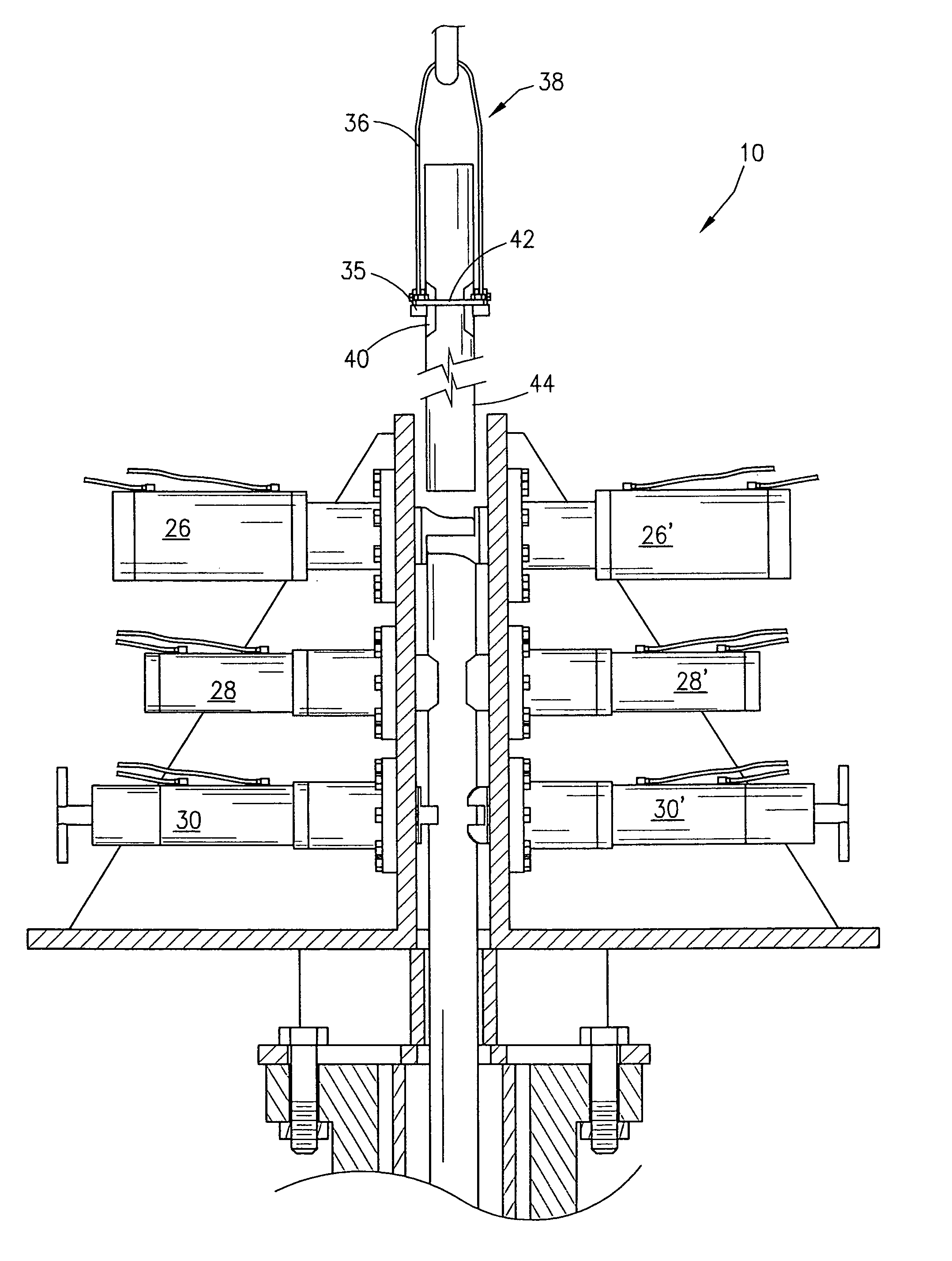
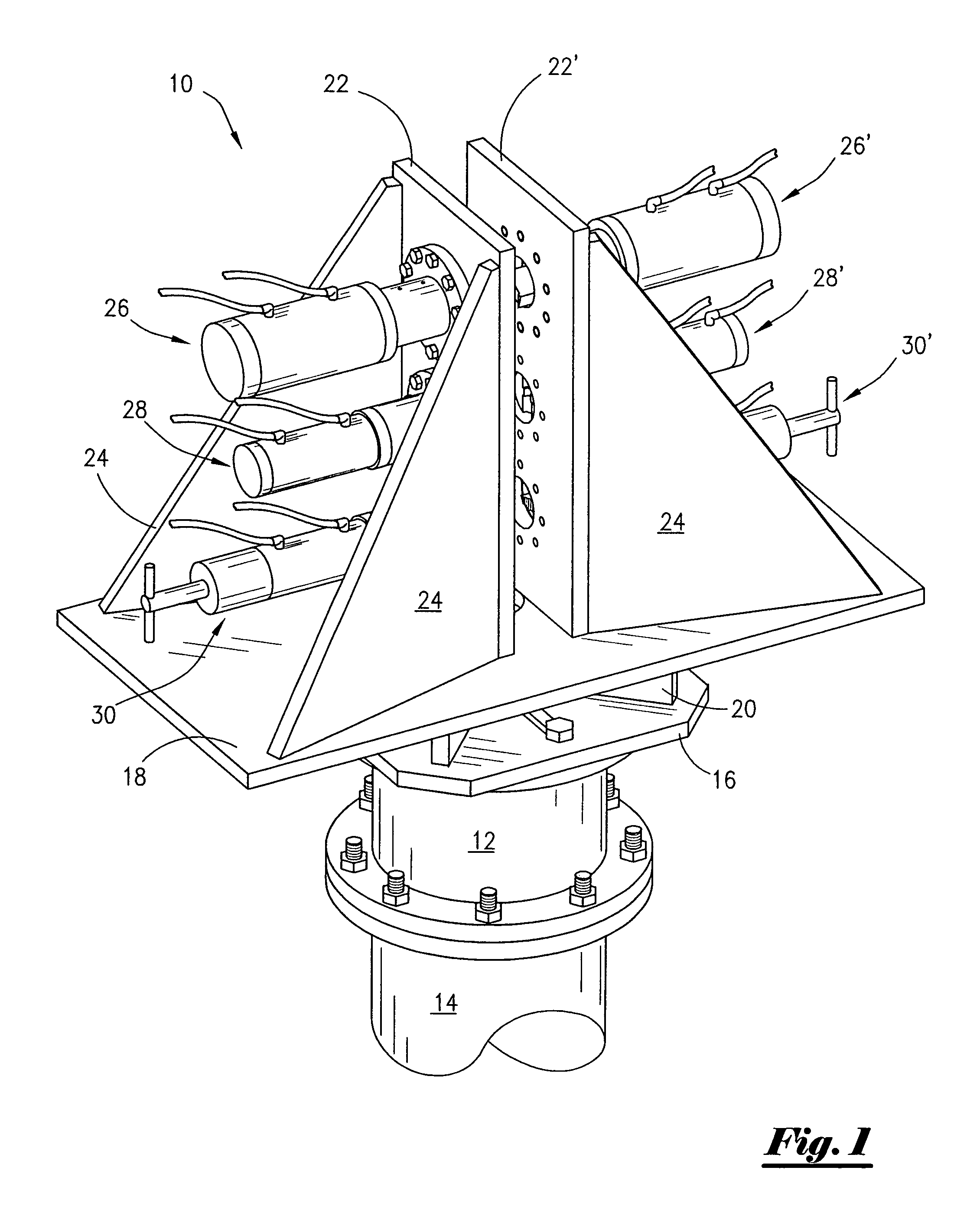
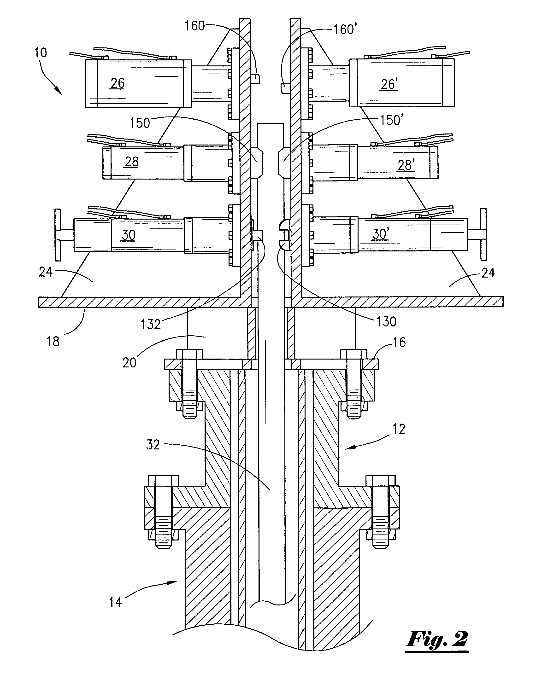
[0042]As may be seen in FIG. 1, the tubular extraction or removal system 10 is a structural mounting, which may be supported in any number of ways over a tubular string to be extracted. Applicant anticipates that an actuator mounting may be supported by an existing structure, suspended, or supported utilizing a variety of support frame configurations utilizing structures using legs etc. Applicant also anticipate that even the mounting assembly 10 itself may be configured in any number of ways for attaching the actuators 26,26′, 28,28′ and 30,30′ in a manner whereby the actuators are opposing each other so as to allow the gripping, indenting and shearing of a tubular string passing there between. Therefore, the structures illustrated herein are not intended to be restrictive in any way. One example of such a mounting is shown in FIG. 1 where a mounting assembly 10 is attached and supported by a wellhead adaptor assembly such as a tubular hanger or flanged adaptor spool 12 and or well...


PUM


Abstract

A tubular extraction system for use in a plug and abandonment process and may include a structural mounting for adaptation to a well head, various mountings may be used to provide a structure for attaching actuators for griping the tubular string, indenting or crimping the tubular and shearing the tubular string. The system further use a fork supported on a lifting apparatus such as a top drive unit, draw works or portable crane, the fork is inserted within the mounting structure of the system to engage the crimped or indented portion of the tubular section being extracted and thus allow removal of sequentially sheared sections of the tubular string.

Description

1. FIELD OF THE INVENTION[0001]The present invention relates generally to oil and gas wells and more specifically to a well head assembly and method for removing tubular from within a well bore during the well's abandonment process.2. GENERAL BACKGROUND[0002]In accordance with the general practice within the oil and gas exploration industry, wells are drilled into the earth in hopes of recovering oil and gas from reservoirs. The drilling process involves the process of installing pipe from the reservoir to the surface. To achieve this, a reinforcing wall is established in the earth in the form of a protective pipe liner called a tubular within the well bore. The casing, in descending diameters, extends in many cases to hundreds of feet and may be cemented in place to ensure a pressure-tight connection between the surface and the oil and gas reservoir. Often cement is placed within the annulus located between the descending diameters, thereby insuring continuity and pressure integrit...

Claims


Application Information

Patent Timeline
Patent Type & Authority Patents(United States)
IPC IPC(8): E21B29/00
CPCE21B19/06E21B29/00E21B33/063
Inventor FANGUY, ROBERT P.
Owner FANGUY ROBERT P
Why Eureka
Try Eureka