
Shower head

a shower head and shower head technology, applied in the field of shower heads, can solve the problems of relatively complicated production of these known shower heads, and achieve the effect of reducing the risk of nozzle-like outlet opening furring and easy modification

Inactive Publication Date: 2010-11-16
HANSA METALLWERKE AG
View PDF12 Cites 61 Cited by
  • Summary
  • Abstract
  • Description
  • Claims
  • Application Information

AI Technical Summary

Benefits of technology

[0009]An object of the present invention is to design a shower head of the type mentioned at the outset such that the production is simplified and the for form is favourable.
[0014]The described design according to the invention can be easily modified in that the interior space of the second part between upper part and lower part is subdivided by at least one partition wall into at least two partial spaces which can be supplied with water independently of one another. In this way, different jet forms can be produced, since the water can be led in each case through different groups of nozzle-like outlet openings which are each associated with one of the partial spaces capable of being supplied independently.

Problems solved by technology

Moreover, the production of these known shower heads is relatively complicated.

Method used


Image

  • Shower head
  • Shower head
  • Shower head

Examples


Embodiment Construction

[0024]While this invention is susceptible of embodiment in many different forms, there is shown in the drawings and will herein be described in detail one or more embodiments with the understanding that the present disclosure is to be considered as an exemplification of the principles of the invention and is not intended to limit the invention to the embodiments illustrated.

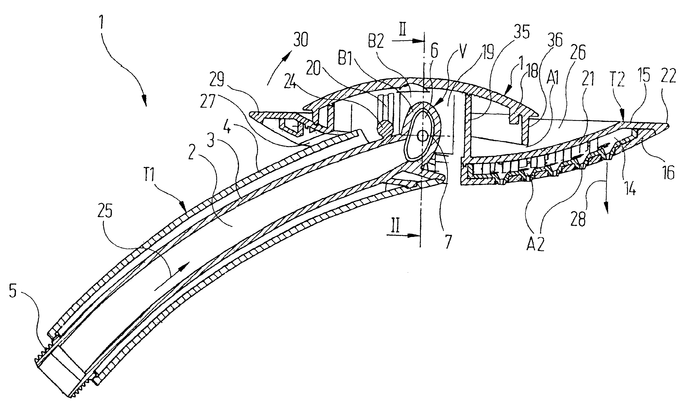
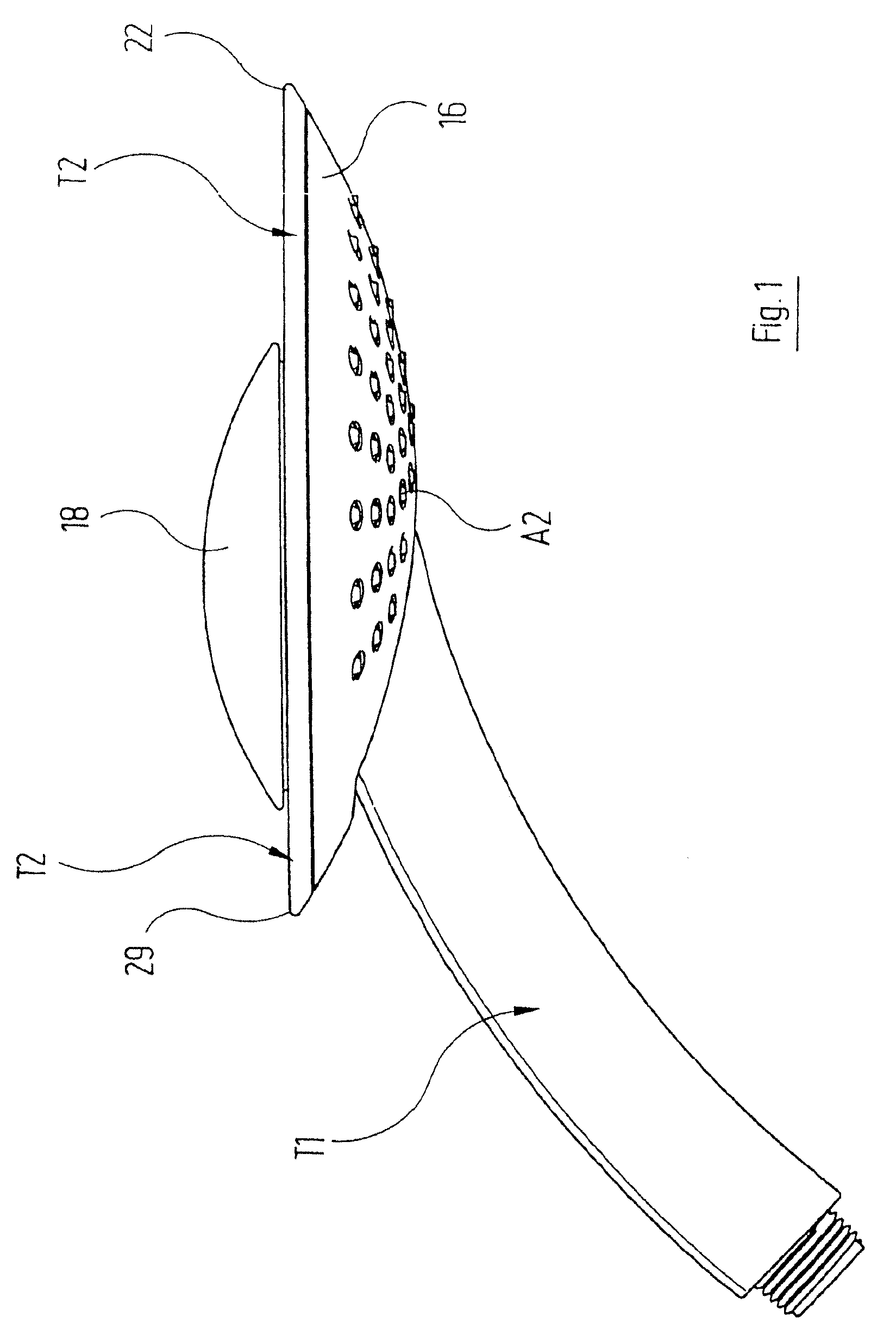
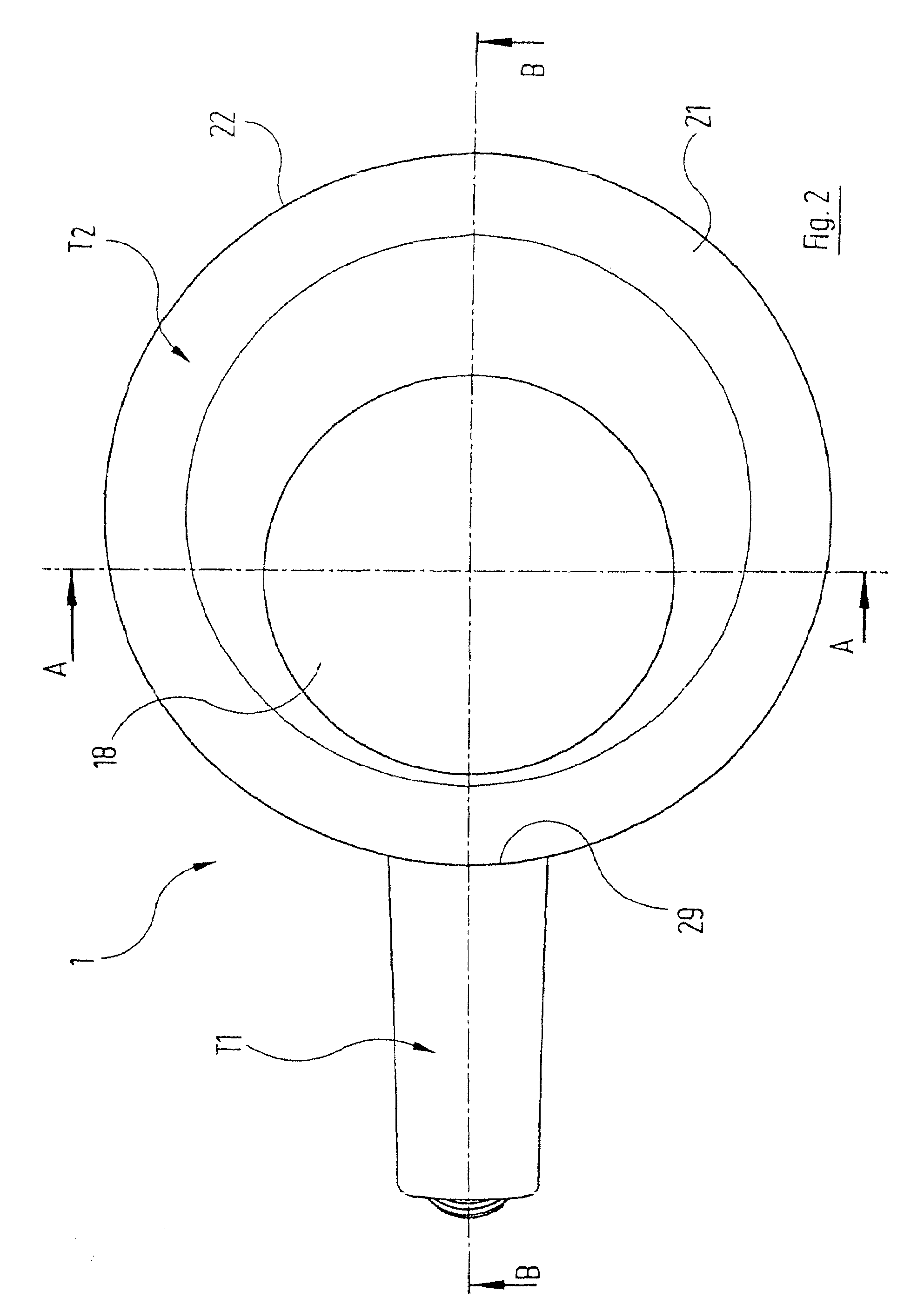
[0025]The shower head 1 illustrated in the drawing is intended for a shower and has a first part T1 and a second part T2. As can be seen in particular from FIGS. 3 and 4, the first part T1 comprises in a tubular housing 4 a water-guiding pipe 3, which forms a water-guiding channel 2. The water-guiding pipe 3 has at one end a water inflow opening which is surrounded by a thread 5 and to which a water conduit (not shown here), for example a flexible tube, is to be connected. The water is supplied to the second part T2, in a manner described in more detail hereinbelow, via a switching valve V.

[0026]The second part T...


PUM


Abstract

Disclosed is a shower head comprising a housing-type first part (T1) inside which a water duct extends. One end of said water duct communicates with a water inlet. The first part (T1) is connected to a second part (T2) that is embodied as a discharging element. The receiving space of the discharging element communicates with the other end of the water duct in at least one mode of operation of the shower head. In said mode of operation, the external edge of the second part (T2) forms an overflow edge in one region, via which water can flow off. The second part (T2) forming the discharging element is composed of a top portion and a bottom portion, between which an interior space is located that communicates with the second end of the water duct in a second mode of operation of the shower head. A plurality of nozzle-type discharge ports (A2) are arranged in the bottom portion of the second part (T2). The inventive shower head is inexpensive to produce while being able to alternatively or cumulatively generate a water curtain discharged via the overflow edge and / or a plurality of individual shower jets discharged through the nozzle-type discharge ports (A2).

Description

RELATED APPLICATIONS[0001]This application claims the filing benefit of International Patent Application No. PCT / EP2006 / 007669, filed Aug. 3, 2006, which claims the filing benefit of Germany Patent Application No. 10 2005 041 143.6 filed Aug. 30, 2005, the contents of which are incorporated herein by reference.TECHNICAL FIELD[0002]The invention relates to a shower head for a shower having[0003]a) a housing-like first part, in which runs a water-guiding channel which communicates, at a first end, with a water inflow opening;[0004]b) a second part, which is connected to the first part and is formed as an outflow element, the receiving space of which communicates with a second end of the water-guiding channel in at least one mode of operation of the shower head, and the outer border of which, in this mode of operation, forms in one region an overflow edge via which water can flow off;[0005]c) the second part additionally having a plurality of nozzle-like outlet openings which communica...

Claims


Application Information

Patent Timeline
IPC IPC(8): B05B15/08B05B15/68
CPCB05B1/1663B05B1/18B05B1/36
Inventor GALLO, DINA
Owner HANSA METALLWERKE AG
Learn More