
Bendable post

a post and flexible technology, applied in the field of bendable posts, can solve the problems of shifting the cost of replacement signage, affecting the use of signage, and accumulating into a significant expense to repair damages and broken signage, so as to reduce post and vehicle damage and costs, and be economical to us

Active Publication Date: 2010-11-16
FLEXPOST
View PDF43 Cites 22 Cited by
  • Summary
  • Abstract
  • Description
  • Claims
  • Application Information

AI Technical Summary

Benefits of technology

[0005]Accordingly, a bendable post of the invention provides an unique answer to the dilemma of impact damage to sign and mailbox posts and the like, with a sturdy and resilient post mount that diminishes post and vehicle damage and costs, is economical to use, and provides desirable performance in various environments.

Problems solved by technology

Vehicle damage to sign posts and the like is commonly known and frequently occurs in many varied situations, which accumulates into a significant expense to repair damages and broken signage.
Conversely, damage from vehicle and sign encounters also results in expensive damages to the vehicles.
These attempts have generally resulted in “disposable” signage that is sacrificed in deference to the vehicle, with associated shift of expense to replacement signage.
Alternatively, the result has been compromised signage that may, at best, not shift cost to the signage, but also does not provide acceptable sign performance, including signs that may wobble or not stand.

Method used


Image

  • Bendable post
  • Bendable post
  • Bendable post

Examples


Embodiment Construction

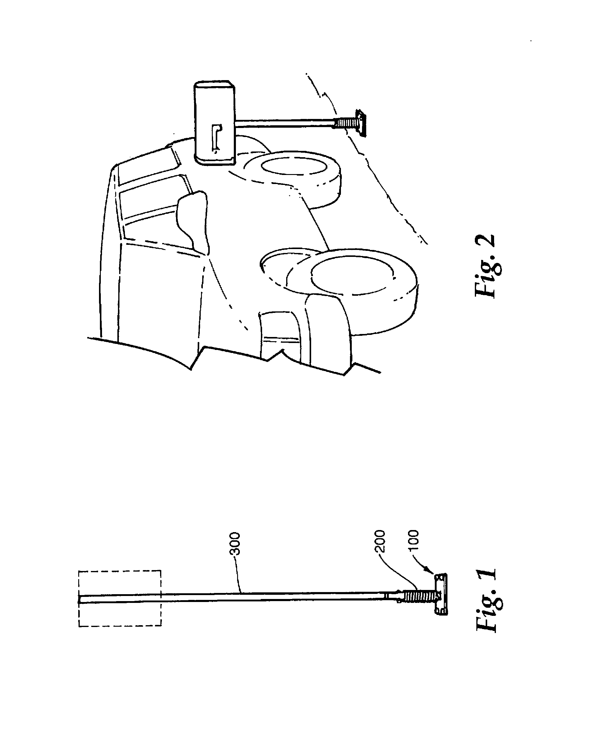
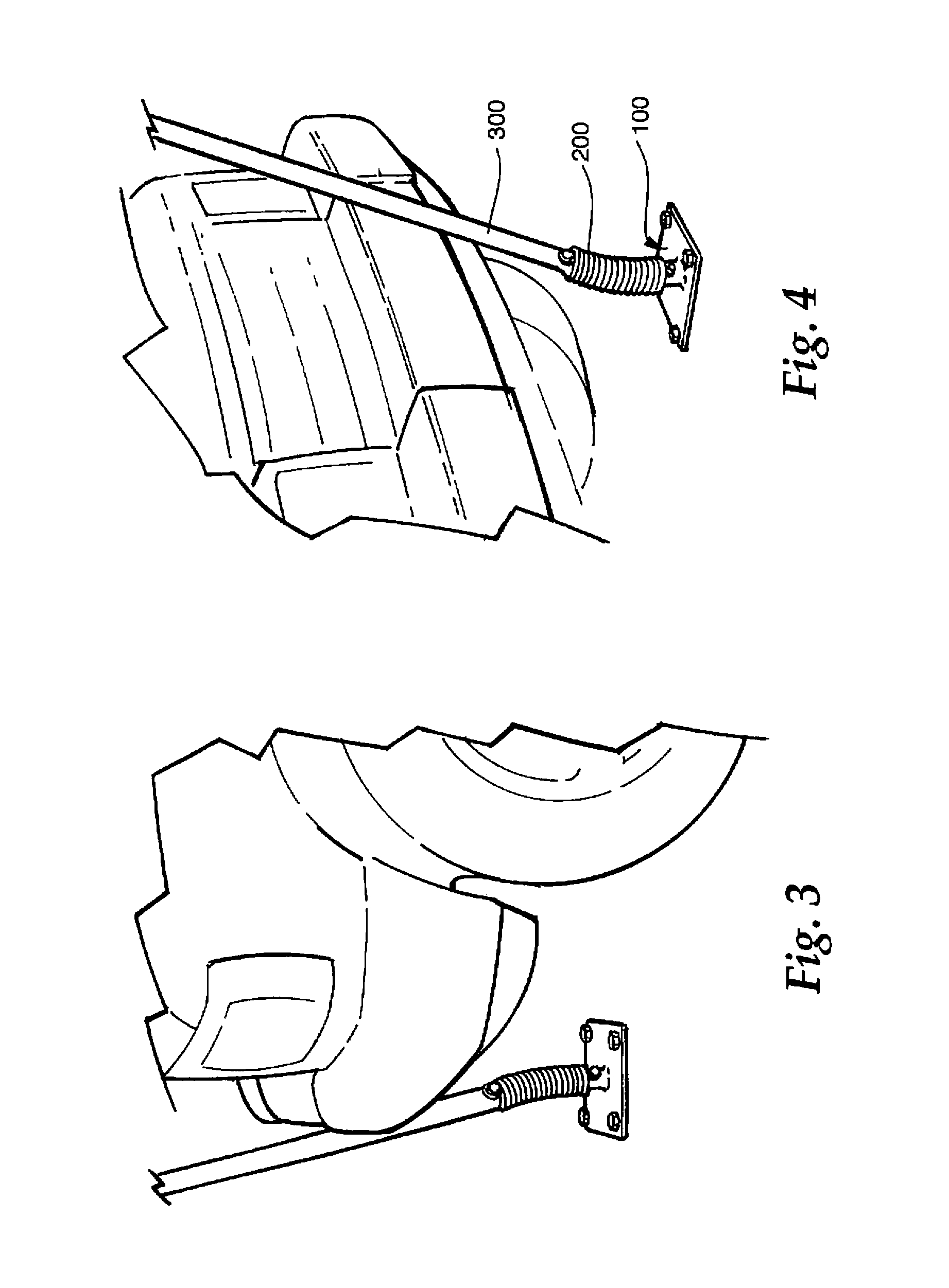
[0067]A preferred embodiment of a bendable post according to the invention is generally shown in the drawing figures and discussed below. A bendable post of the invention may be utilized in various installations including a mailbox post (FIGS. 2 and 49-52), a pavement placed sign post (FIGS. 1, 3-10, and 14-39), and a dirt placed sign post (FIGS. 10-13, 20-23, and 32-48).

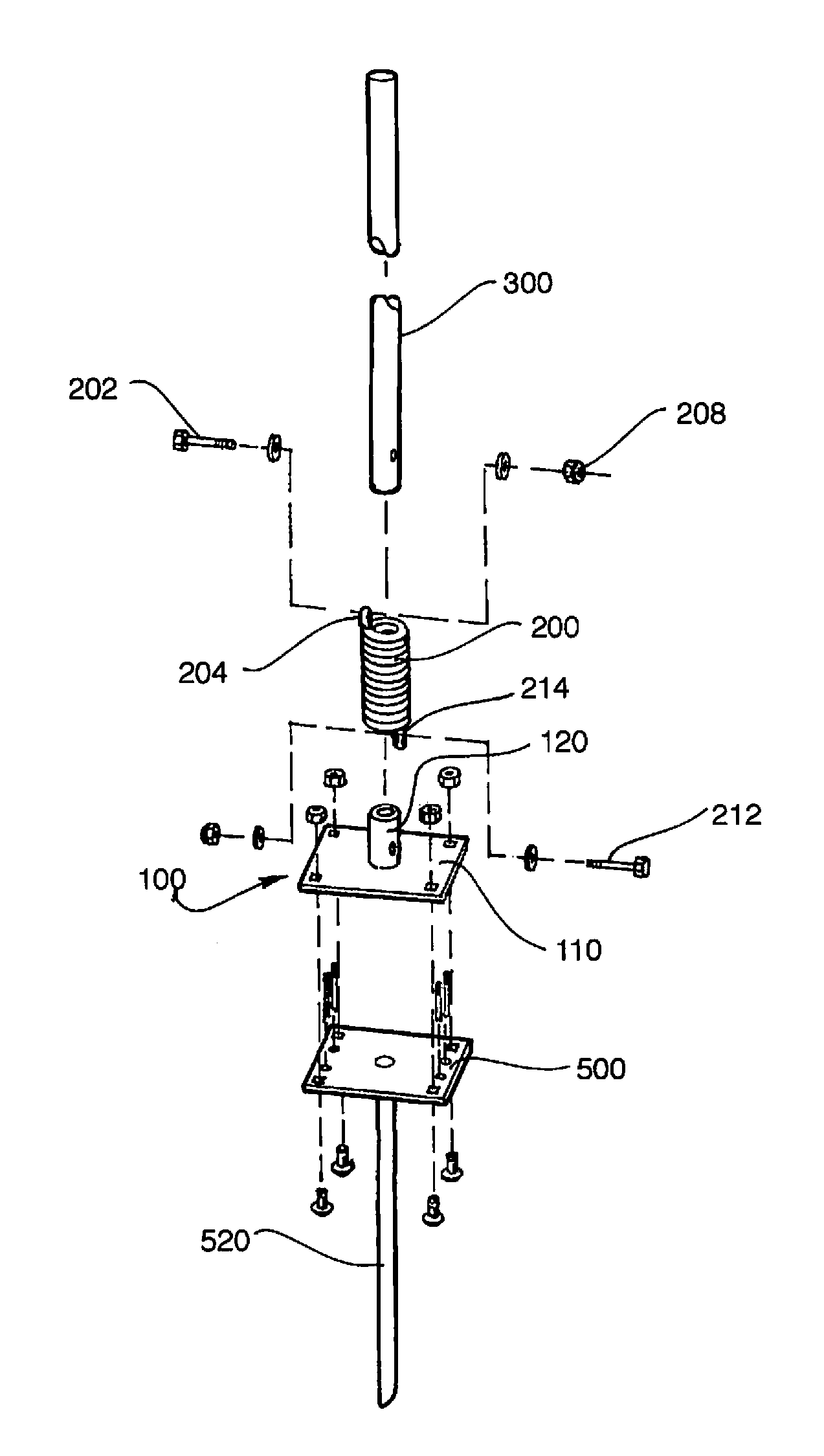
[0068]Addressing the common components of the various bendable post adaptations, each bendable post has a foundation assembly, a top assembly 100, a helical coil spring 200 (FIGS. 55-58), and an upper post 300. The foundation assembly may vary according to specific mounting situations.

[0069]The upper post 300 may be of any suitable construction for a sign application or the like of interest and in the present example may include a 1.625 inch (41.3 mm) outside diameter SS20 galvanized steel post (FIGS. 1-6, 15, and 40). Various color treatments may be optionally applied, including painting, powder coating, and sheath...


PUM


Abstract

A bendable mailbox or sign post comprises a foundation defined at one of a dirt, a concrete, and an asphalt surface. A top assembly releasably couples with the foundation and has a plate and a stub extending upward from the plate. The elongated post extends vertically from a bottom end connected with the top assembly. A resilient interconnection is provided between the post and the top assembly, whereby the post pivots about the bottom end and deflects from its vertical orientation when a lateral force is applied to the post and the post returns to the vertical orientation when no lateral force is applied. A frangible interconnection may be provided between the resilient interconnection member and one of the post and the stub.

Description

CROSS-REFERENCE TO RELATED APPLICATIONS[0001]This application is based on and claims the priority date of Applicant's co-pending U.S. Provisional Patent Application Ser. No. 60 / 786,512, entitled BENDABLE POST and filed on Mar. 28, 2006, by Thomas A. Ebel and Brian Kronenmeyer, the disclosure of which is incorporated herein by reference.BACKGROUND OF THE INVENTION[0002]The invention relates to sign posts, mailbox posts, and the like. More specifically, the invention includes a damage resistant flexible post mount that provides a stable post mount, which deflects under lateral loading, such as being pushed by a vehicle, and returns to its unloaded, upright condition.[0003]Vehicle damage to sign posts and the like is commonly known and frequently occurs in many varied situations, which accumulates into a significant expense to repair damages and broken signage. Conversely, damage from vehicle and sign encounters also results in expensive damages to the vehicles.[0004]While attempts hav...

Claims


Application Information

Patent Timeline
Patent Type & Authority Patents(United States)
IPC IPC(8): A45F3/44
CPCE01F9/0175Y10S248/90Y10T403/11E01F9/629F16B2200/63
Inventor EBEL, THOMAS A.KRONENMEYER, BRIAN
Owner FLEXPOST
Learn More