
Simulated edged weapon or toy with element actuated indicating device

a technology of indicating device and simulated edged weapon, which is applied in the field of apparatus simulating edged weapon or toy, can solve the problems of human error, device being used in a game or competition, and not being realistic,

Inactive Publication Date: 2010-11-16
HORVATH DWAYNE A
View PDF19 Cites 13 Cited by
  • Summary
  • Abstract
  • Description
  • Claims
  • Application Information

AI Technical Summary

Benefits of technology

"The patent describes a toy or weapon that can be simulated to have a sharp edge. It has a housing and a part that moves in response to force. The toy has a circuit that lights up when it moves. The movement is detected by a sensor and an indicator device is turned on."

Problems solved by technology

Some exercises start with the knife touching a body part simulating a threat, in this case, the ink marking devices would leave a mark on ones throat or arm before the defensive exercise begins and would not be realistic.
These devices being used in a game or competition also have no way to convey a strike electronically to an indicating device(s) or wireless remote receiver(s).
Since a judge or judges are required to visually confirm the first strike, this can be hard to see in the fast movement of competition thereby being subject to human error.
Other dull element training or toy knives have no means to convey contact at all.
In a class or group setting, the instructor has no way of readily seeing who is being cut or stabbed to correct mistakes.
This design suffers from several weaknesses.
In competition, strikes can be delivered so quickly thus making it difficult to determine who was struck first without the use of an electronic signaling device.
In use when performing training drills, moves or strikes are performed in repetition as well as general self defense drills practiced requiring blade contact to a body part first, making training unrealistic as well as uncomfortable and leaving marks all over ones body.

Method used


Image

  • Simulated edged weapon or toy with element actuated indicating device
  • Simulated edged weapon or toy with element actuated indicating device
  • Simulated edged weapon or toy with element actuated indicating device

Examples


second embodiment

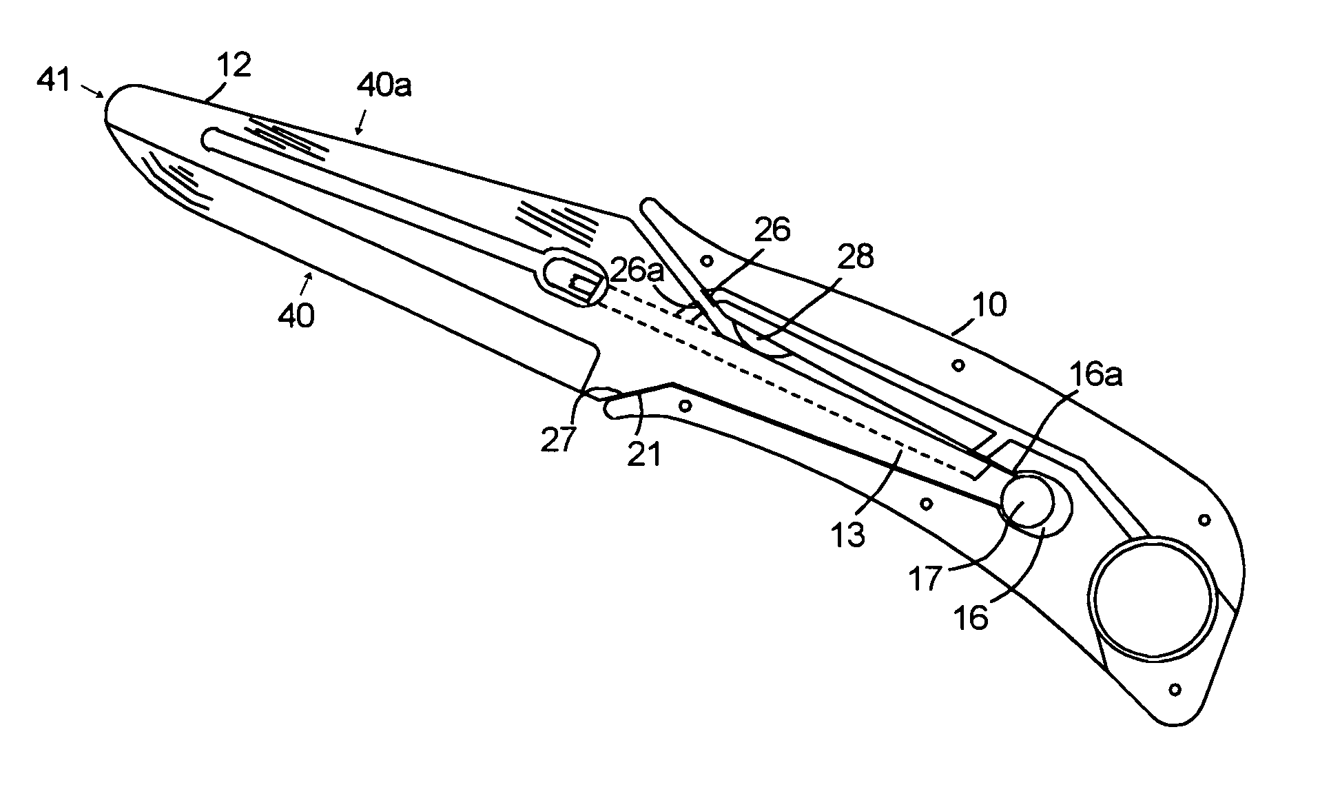
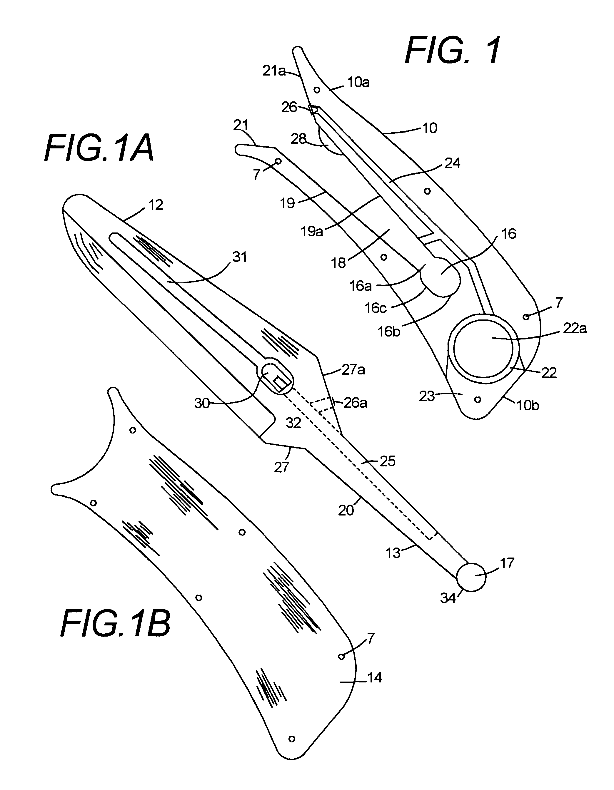
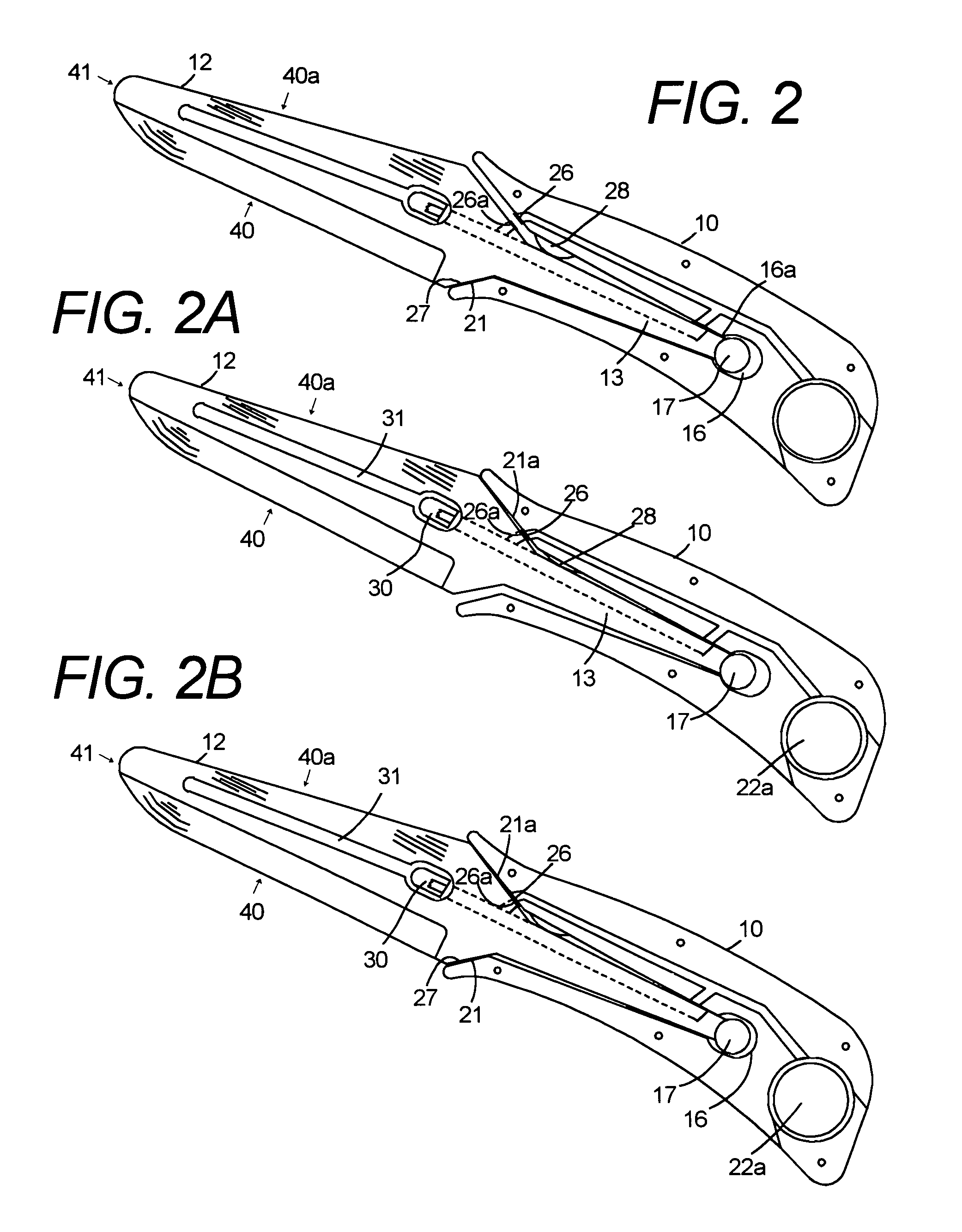
[0061]FIG. 3A shows a second embodiment for moveably retaining the element 12 in the housing 10. This embodiment is similar to the first detailed above with the differences as follows. An elongate slot 45 having a forward end 45a, a rearward end 45b, and a width 45c, is disposed in the tang 13 between the tang first end 32 and second end 34 generally longitudinal to the element 12. In this embodiment the elongate slot is disposed near the second end 34 of the tang 13. A rod 47 being no larger than the elongate slot width 45c extends through the elongate slot 45 at the rearward end 45b and is secured to the housing 10.

[0062]In operation this embodiment works the same as the preferred embodiment with the rod 47 moveably retaining the element 12 in the housing 10. The rod 47 is disposed through the rearward end 45b of the elongate slot 45 retaining yet allowing the element 12 to move in compound directions in relation to the housing 10 in response to a force on the element.

[0063]FIG. 4...

third embodiment

[0064]FIG. 3B shows a third embodiment for moveably retaining the element 12 in the housing 10 with the differences as follows. The tang 13 having a top edge 52 and a bottom edge 54 and the second end 34 is substantially surrounded by a resilient material 50 allowing for movement of the element 12 in relation to the housing 10. The resilient material 50 having a firmness that allows the element 12 to maintain an unswitched position and a softness that allows the element to be moveable in response to a force on the element 12. The cut out 18 in the housing 10 having a complementary shape of the tang 13 to allow for the resilient material 50 to reside between the tang 13 and the cutout 18. This space allows for movement of the element 12 in one or compound directions as detailed above. This embodiment includes the elongate slot 45 and rod 47 as detailed above to retain the element 12 in the housing 10. In use, all workings will be the same as detailed.

fourth embodiment

[0065]FIG. 4 shows a fourth embodiment using some of the teachings previously described. The same identification will be used as on previously described parts. This embodiment including a movement sensor actuator that includes the battery 22a and a tang 130 being arranged to contact each other completing the circuit upon movement of the element 12.

[0066]The housing rearward end 10b contains a cutout 220 generally located towards the rearward end 10b to house the battery 22a. One side of the cutout is open resembling a C exposing a portion of the battery 22a to a forward extending cutout 180 having a top wall 18a and a bottom wall 18b. Cutout 180 continues forward to the larger angled wedged shaped cutout 21 and 21a. The larger angle wedged shaped cutout continues through to the outer edges of the housing 10. The bottom wall 18b is a straight cut from angle 21 intersecting the battery cutout 220 opening lower edge. The top wall 18a is a straight cut from angle 21a to a fin shaped end...


PUM


Abstract

A simulated sharp edged weapon or toy comprising a housing, an element mounted in and extending from said housing arranged such that said element has movement in relation to said housing in response to force upon said element, an electrical circuit mounted in said housing for providing an indication upon activation having a movement sensor actuator mounted in cooperation with said element to turn on at least one indicating device providing indication of movement of said element.

Description

CROSS REFERENCE TO RELATED APPLICATIONS[0001]Not ApplicableFEDERALLY SPONSORED RESEARCH[0002]Not ApplicableSEQUENCE LISTING OR PROGRAM[0003]Not ApplicableBACKGROUND OF THE INVENTION[0004]1. Field of Invention[0005]The present invention relates generally to an apparatus simulating an edged weapon or toy wherein the same is arranged to alert contact.[0006]2. Discussion of Prior Art[0007]A large number of groups teach knife self-defense and combat training, including martial arts schools, law enforcement and the military. Most groups use wooden knives, rubber knives, or dull aluminum knives. More recently marking devices have been used show where the element makes contact, however a marking device stains, not only on ones clothing but also on the mat and anything else it touches.[0008]Some exercises start with the knife touching a body part simulating a threat, in this case, the ink marking devices would leave a mark on ones throat or arm before the defensive exercise begins and would ...

Claims


Application Information

Patent Timeline
Patent Type & Authority Patents(United States)
IPC IPC(8): A63B69/00
CPCA63B69/00A63B69/004A63B69/02A63B71/06A63B2069/0044A63B2220/17A63B2225/50A63B2244/10A63B69/333
Inventor HORVATH, DWAYNE A
Owner HORVATH DWAYNE A
Learn More