Surgical guides and methods for positioning artificial teeth and dental implants

a technology of surgical guides and implants, applied in dental surgery, impression caps, instruments, etc., can solve the problems of difficult to determine the actual shape of teeth, difficult to image these areas, and consuming process

Inactive Publication Date: 2010-11-16
VOXELOGIX CORP
View PDF159 Cites 31 Cited by
  • Summary
  • Abstract
  • Description
  • Claims
  • Application Information

AI Technical Summary

Benefits of technology

[0007]U.S. patent application Ser. No. 11 / 674,956, titled Method for Making a Virtual Computer Model of the Jaws, filed Feb. 14, 2007, incorporated herein in its entirety by reference, reveals a method of using computed tomography (CT) to image the hard and soft tissues of the head and neck. It also reveals a method of imaging dental casts of a patient using non-radiographic techniques to eliminate radiographic scatter caused by dental restorations in CT scans.
[0012]In some embodiments, the exemplary methods and systems disclosed herein provide a method for the surgeon and restorative dentist to virtually reshape bone to provide adequate space for restorative materials and to create an ideal osseous form for implant placement.

Problems solved by technology

This is a time consuming process since a dental laboratory technician must set or carve teeth to fit in the ideal position for a given patient.
If the patient has teeth that will be removed at the time of implant placement it is difficult to image these areas since the teeth are still present and frequently radiographic scatter makes it difficult to determine the actual shape of the teeth.
It is also difficult to position the template in a predictable position after the teeth are removed.
This system allows for planning of the dental implant position in relation to the patient's denture and the supporting bone but it does not allow for planning the shape of the bone if reshaping is needed to have adequate space for restorative materials or to have the proper ridge form for the dental implant.
This system also does not allow for changes in the position of the artificial teeth after the denture has been imaged.

Method used


Image

  • Surgical guides and methods for positioning artificial teeth and dental implants
  • Surgical guides and methods for positioning artificial teeth and dental implants
  • Surgical guides and methods for positioning artificial teeth and dental implants

Examples


Embodiment Construction

[0039]For the purposes of promoting an understanding of the principles of the invention, reference will now be made to embodiments, or examples, illustrated in the drawings and specific language will be used to describe the same. It will nevertheless be understood that no limitation of the scope of the invention is thereby intended. Any alterations and further modifications in the described embodiments, and any further applications of the principles of the invention as described herein are contemplated as would normally occur to one skilled in the art to which the invention relates.

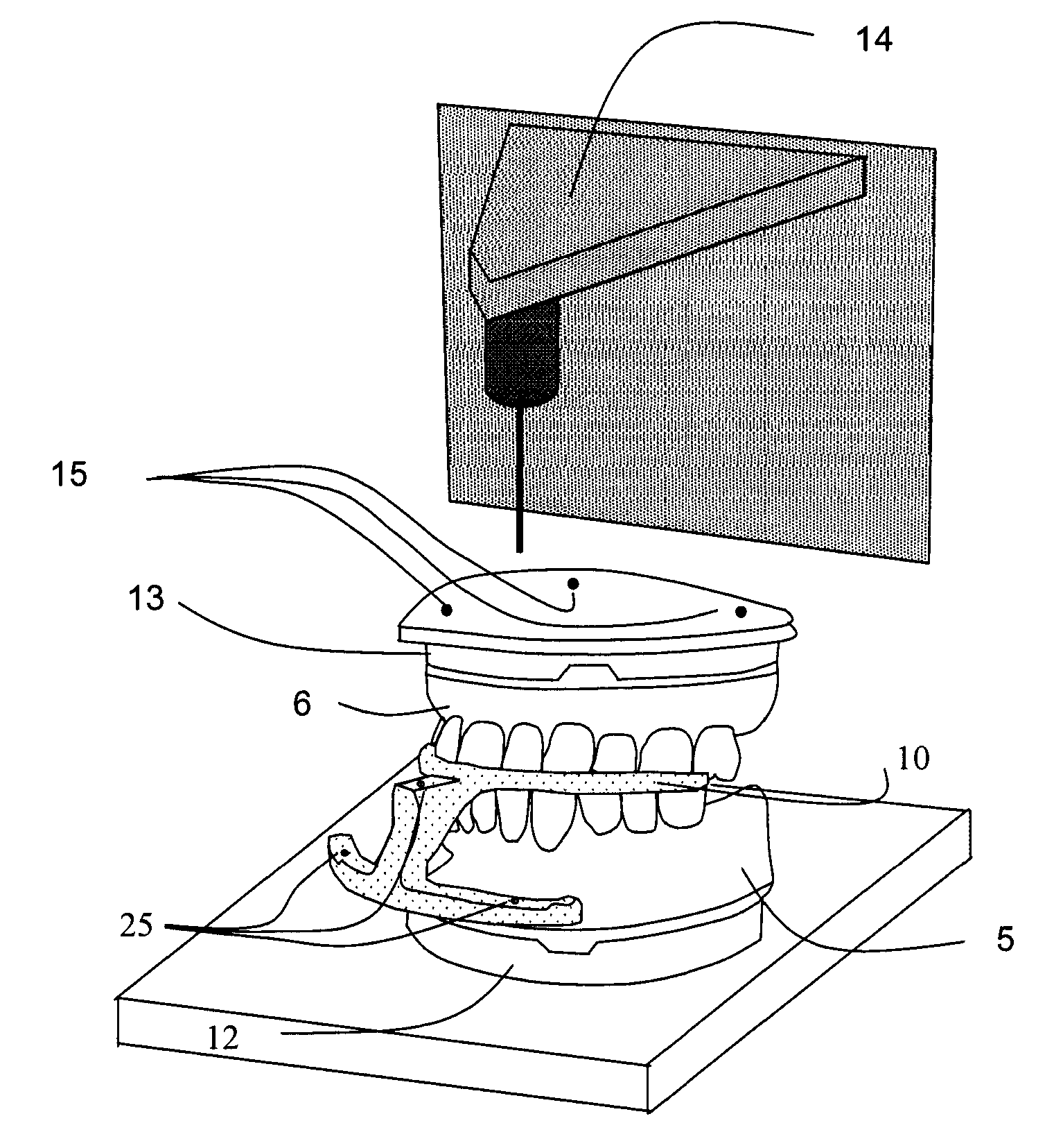
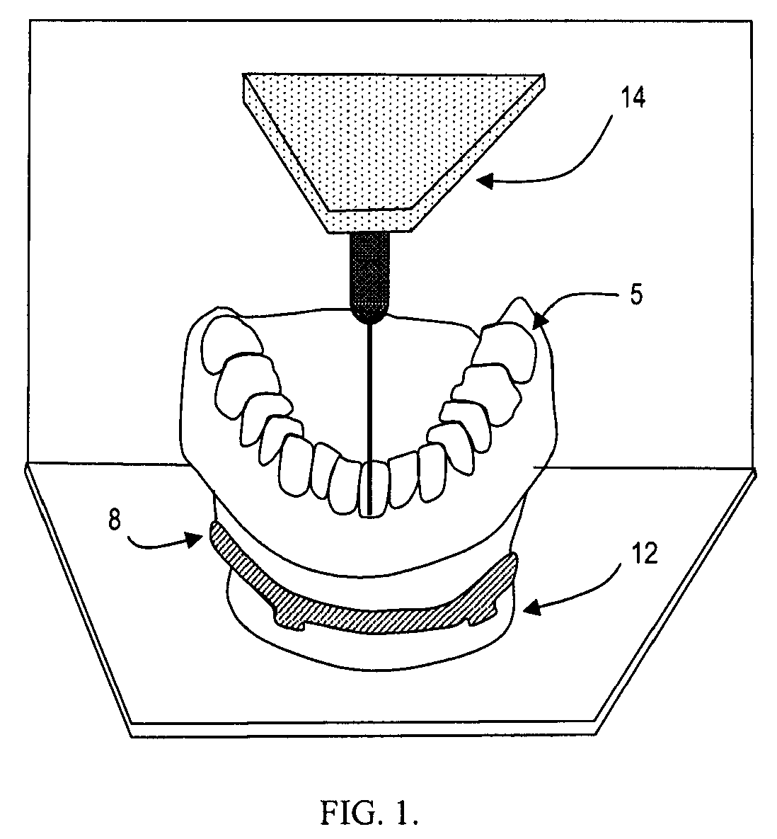
[0040]FIG. 1 illustrates a lower cast 5 joined to a mounting plate 8 seated in a mounting plate receiver 12. The cast 5 is positioned in a digital imaging system 14 and can be imaged with contact, light, laser, radiographic, or holographic imaging techniques. The imaging system creates a data set of the 3D surface of the dental cast 5 in a known spatial relationship to the mounting plate receiver 12. The ...


PUM


Abstract

A method is set forth for making a computer model of patient's jaws on the basis of digital information. Digital data about the jaws, teeth, soft tissues and artificial teeth is joined in computer space to create aesthetic and functional plans for the removal of teeth, shaping of supporting bone and placement of dental implants. Artificial teeth and pre-manufactured prosthetic devices are made and attached to the dental implants at the time of surgery. The aesthetic and functional position of artificial teeth is determined prior to surgical removal of natural teeth and the ideal position of implants and the proper form of the remaining bone are determined prior to surgery. Surgical guides used to shape bone, record occlusal orientation and position dental implants are manufactured using computer milling or layered manufacturing.

Description

PRIORITY INFORMATION[0001]This disclosure claims priority to and the benefit of the filing date of U.S. Provisional Application No. 60 / 849,994, filed Oct. 7, 2006, incorporated herein by reference.FIELD OF THE INVENTION[0002]The present disclosure is directed to methods of evaluating and treating a patient's anatomy prior to tooth removal and planning the ideal position of artificial teeth. It also is directed to methods for the computer manufacture of artificial teeth attached to dental implants.BACKGROUND OF THE INVENTION[0003]Patient preparation and implantation of dental implants may be accomplished in different ways. For example, one method uses a radiographic template made to fit to the patient's teeth. Radiographic markers are attached to this template. Another method, disclosed in U.S. Pat. No. 5,967,777 to Klein, uses a plastic replica of the prospective teeth to be supported by dental implants. This is a time consuming process since a dental laboratory technician must set ...

Claims


Application Information

Patent Timeline
Patent Type & Authority Patents(United States)
IPC IPC(8): G06F19/00G16Z99/00
CPCA61C1/084A61C13/0004A61C8/0001A61C19/045A61C9/0046G16H50/50B33Y80/00G16Z99/00
Inventor SCHMITT, STEPHEN M.
Owner VOXELOGIX CORP
Why Eureka
Try Eureka