Method and device for calibrating a magnetic sensor

a magnetic sensor and calibration method technology, applied in the field of magnetic sensor calibration, can solve the problems of not being repeatable after installation of the magnetic sensor, not easily available, and not being useful for compensating with known calibration methods

Inactive Publication Date: 2010-11-16
STMICROELECTRONICS SRL
View PDF13 Cites 17 Cited by
  • Summary
  • Abstract
  • Description
  • Claims
  • Application Information

AI Technical Summary

Benefits of technology

[0009]Disclosed herein is a method of calibration of a magnetic sensor that may enable at least some of the limitations described to be overcome and, in particular, may enable calibration to be carried out also after installation of the magnetic sensor in a user device.

Problems solved by technology

The methods of this type, however, present the disadvantage of not being repeatable after installation of the magnetic sensor because it is necessary to restore well-defined environmental conditions and carry out accurate rotations of the magnetic sensor according to degrees of freedom that are often no longer available.
Furthermore, calibration as described necessarily requires the comparison with a value of magnetic field supplied by an already calibrated reference, which is not easily available.
Consequently, albeit precise and accurate they may be, known calibration methods are not useful for compensating for the effects of sources of disturbance and error that intervene after the magnetic sensor has been set in operation.
In this case, the method is irrespective of the availability of a previously calibrated reference, but does not enable calibration of the gain values.

Method used


Image

  • Method and device for calibrating a magnetic sensor
  • Method and device for calibrating a magnetic sensor
  • Method and device for calibrating a magnetic sensor

Examples


Embodiment Construction

[0027]In the following description, reference will be made to use of a magnetic sensor or magnetometer in a pointing and control device for a computer system, without this being considered as in any way limiting the scope of the invention. At least some embodiments can be in fact exploited for calibration of any magnetic sensor, for use in a variety of applications, such as, for example, compasses or navigation systems.

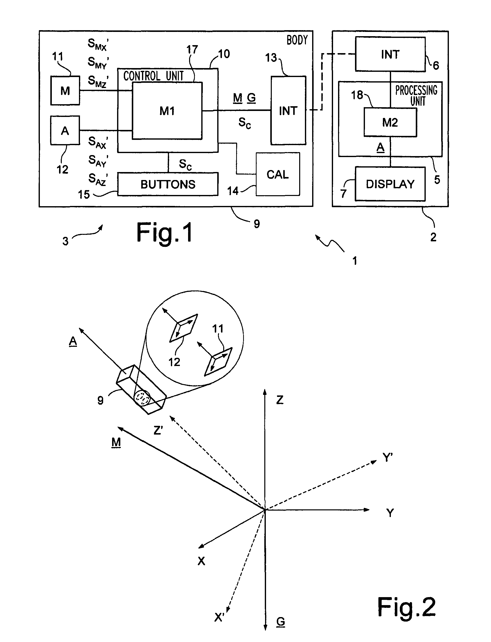
[0028]With reference to FIG. 1, a computer system, designated as a whole by the number 1, comprises a computer 2 and a pointing and control device 3.

[0029]The computer 2 is equipped with a processing unit 5 and further comprises a communication interface 6 and a display 7.

[0030]The pointing and control device 3 comprises a body 9 shaped so as to be maneuverable by a user. Inside the body 9, the pointing and control device 3 further comprises a control unit 10, for example a microcontroller or a DSP (Digital Signal Processor), a magnetometer 11, an inertial sensor, in ...


PUM


Abstract

Measurements are acquired from a magnetic sensor during a non-pre-ordered movement, and a plurality of sets of solutions are determined for respective expected values of intensity of the Earth's magnetic field. The solutions are defined by a plurality of parameters, including at least one gain value for each detection axis of the magnetic sensor. For each solution, a figure of merit is determined, correlated to a calibration error, and a partial solution is selected in each set of solutions, based on the figure of merit. Once a gain confidence interval has been defined, a calibration solution is selected based on the figure of merit, from among the partial solutions having respective gain values all falling within the gain confidence interval.

Description

CROSS-REFERENCE TO RELATED APPLICATION[0001]This application claims priority from and the benefit of the filing date of European Patent Application No. 07425537.3 filed Aug. 23, 2007, the content of which is hereby incorporated herein by reference in its entirety.BACKGROUND[0002]1. Technical Field[0003]The present invention relates generally to calibration of magnetic sensors.[0004]2. Description of the Related Art[0005]It is known to use magnetic sensors for making devices designed to determine an orientation and / or a position of a body, such as, for example, compasses and navigation systems. Magnetic sensors can determine the orientation of their own detection axes with respect to the Earth's magnetic field, which defines a fixed reference with respect to the ground.[0006]Prior to their use, magnetic sensors must be calibrated so as to eliminate or at least reduce any imprecision and disturbance that can derive from different sources, such as, for example, process dispersions duri...

Claims


Application Information

Patent Timeline
Patent Type & Authority Patents(United States)
IPC IPC(8): G01C17/38
CPCG01C17/28G01C17/38G01R33/0206
Inventor VOCALI, FRANCESCOBIGANZOLI, FABIO
Owner STMICROELECTRONICS SRL
Why Eureka
Try Eureka