Morphable bit

a morphable bit technology, applied in the field of drilling, can solve problems such as the veering of the drill bi

Inactive Publication Date: 2010-11-23
SCHLUMBERGER TECH CORP
View PDF82 Cites 37 Cited by
  • Summary
  • Abstract
  • Description
  • Claims
  • Application Information

AI Technical Summary

Problems solved by technology

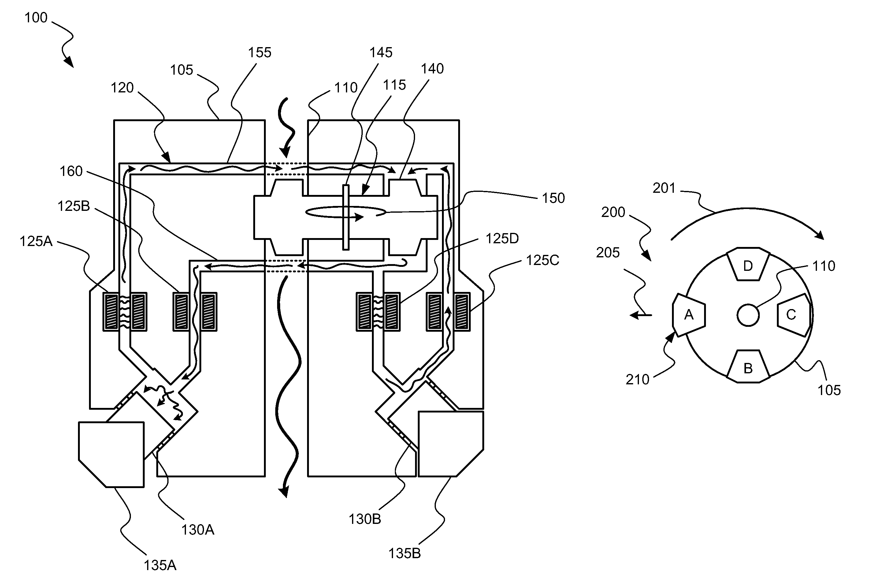
Often the drill bit will veer off of a planned drilling trajectory because of the unpredictable nature of the formations being penetrated or the varying forces that the drill bit experiences.

Method used


Image

  • Morphable bit
  • Morphable bit
  • Morphable bit

Examples


Embodiment Construction

[0019]The ensuing description provides exemplary embodiments only, and is not intended to limit the scope, applicability or configuration of the disclosure. Rather, the ensuing description of the exemplary embodiments will provide those skilled in the art with an enabling description for implementing one or more exemplary embodiments. It being understood that various changes may be made in the function and arrangement of elements without departing from the spirit and scope of the invention as set forth in the appended claims.

[0020]Specific details are given in the following description to provide a thorough understanding of the embodiments. However, it will be understood by one of ordinary skill in the art that the embodiments may be practiced without these specific details. For example, systems, processes, and other elements in the invention may be shown as components in block diagram form in order not to obscure the embodiments in unnecessary detail. In other instances, well-known...


PUM


Abstract

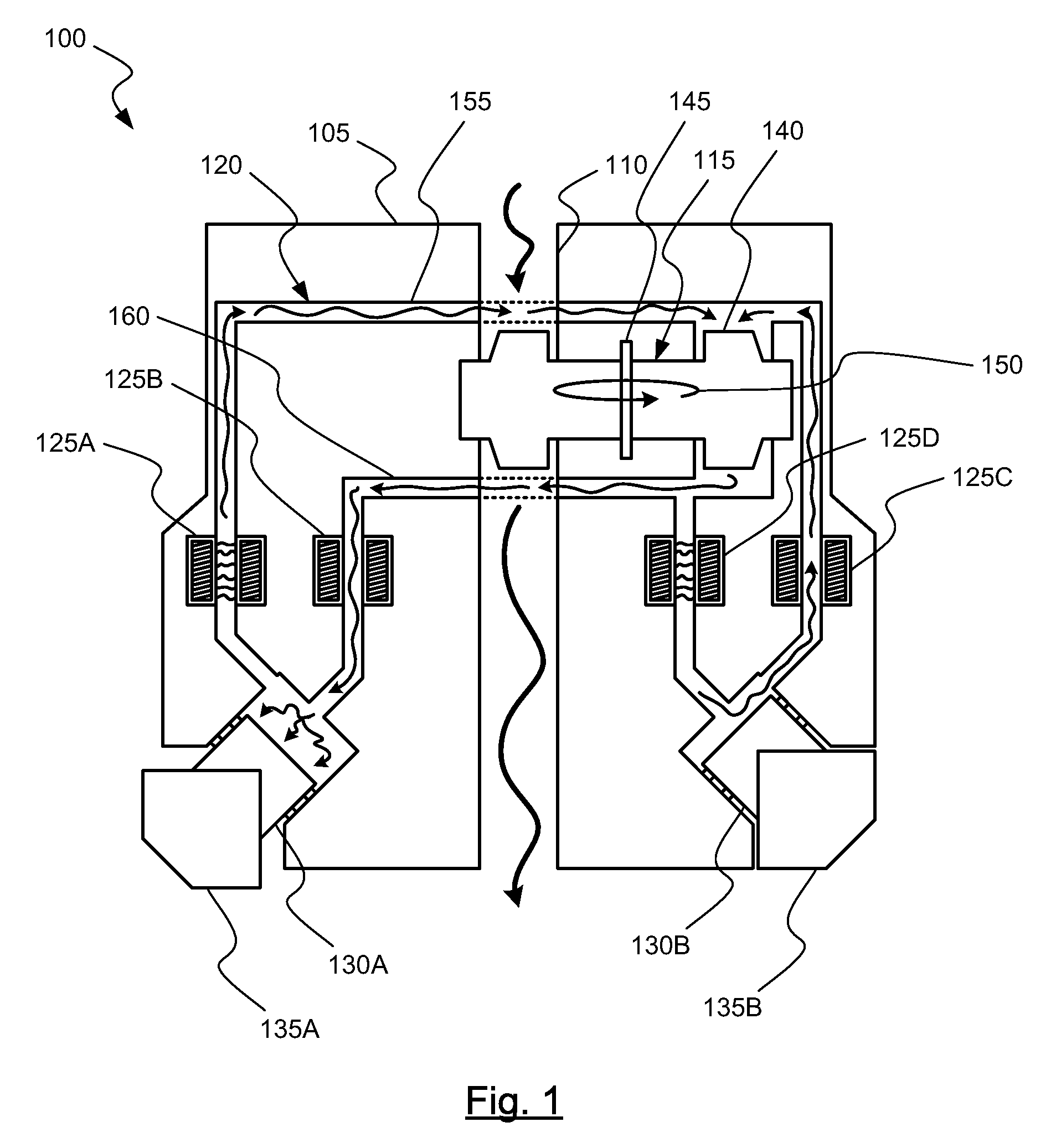
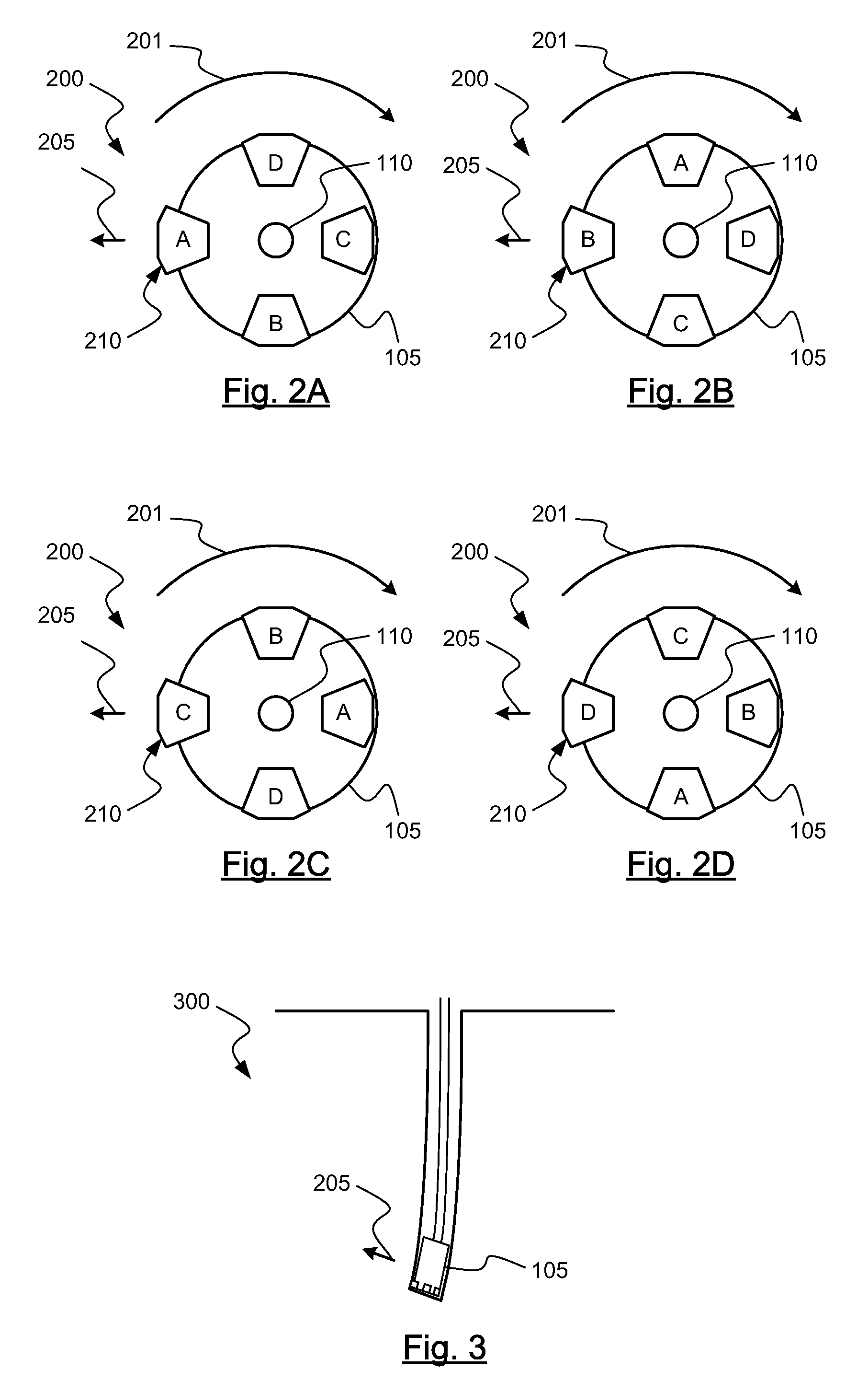
A bottom hole assembly for drilling a cavity including a chassis configured to rotate is provided. The chassis may include a conduit, a circuit, a pressure transfer device, a plurality of pistons, a plurality of valves, and a plurality of cutters. The conduit may accept a first flow of a primary fluid. The circuit may have a second flow of a secondary fluid. The pressure transfer device may be configured to transfer pressure between the flows. The pistons may be operably coupled with the circuit, and each piston may be configured to move based at least in part on a pressure of the circuit at that piston, with the valves possibly configured to control a pressure of the circuit at each piston. Each cutter may be coupled with one of the pistons.

Description

BACKGROUND OF THE INVENTION[0001]This invention relates generally to drilling. More specifically the invention relates to drilling directional holes in earthen formations.[0002]Directional drilling is the intentional deviation of the wellbore from the path it would naturally take. In other words, directional drilling is the steering of the drill string so that it travels in a desired direction.[0003]Directional drilling is advantageous in offshore drilling because it enables many wells to be drilled from a single platform. Directional drilling also enables horizontal drilling through a reservoir. Horizontal drilling enables a longer length of the wellbore to traverse the reservoir, which increases the production rate from the well.[0004]A directional drilling system may also be used in vertical drilling operation as well. Often the drill bit will veer off of a planned drilling trajectory because of the unpredictable nature of the formations being penetrated or the varying forces tha...

Claims


Application Information

Patent Timeline
Patent Type & Authority Patents(United States)
IPC IPC(8): E21B10/38
CPCE21B10/322E21B7/064E21B10/633
Inventor CHEN, KUO-CHIANGDOWNTON, GEOFF
Owner SCHLUMBERGER TECH CORP
Why Eureka
Try Eureka