Hydraulic Lockout Device for Pressure Controlled Well Tools

Inactive Publication Date: 2010-08-12
HALLIBURTON ENERGY SERVICES INC
View PDF42 Cites 33 Cited by
  • Summary
  • Abstract
  • Description
  • Claims
  • Application Information

AI Technical Summary

Benefits of technology

[0011]In yet another aspect, the present invention is directed to a method for selectively preventing and allowing operation of a pressure controlled well tool. The method includes at least partially defining a first chamber operable to contain a compressible fluid, a second chamber operable to contain a substantially incompressible fluid and third chamber operable to contain a power fluid between a mandrel assembly and housing assembly; communicating pressure between the second and third chambers with a power piston disposed therebetween; communicating pressure between the first and second cham

Problems solved by technology

It has been found, however, that certain disadvantages exist where multiple pressure operated tools are utilized in a single tool string.
In some circumstances, this can present a disadvantage in that the releasing and operating pressure for the seco

Method used


Image

  • Hydraulic Lockout Device for Pressure Controlled Well Tools
  • Hydraulic Lockout Device for Pressure Controlled Well Tools
  • Hydraulic Lockout Device for Pressure Controlled Well Tools

Examples


Embodiment Construction

[0023]While the making and using of various embodiments of the present invention are discussed in detail below, it should be appreciated that the present invention provides many applicable inventive concepts, which can be embodied in a wide variety of specific contexts. The specific embodiments discussed herein are merely illustrative of specific ways to make and use the invention, and do not delimit the scope of the invention.

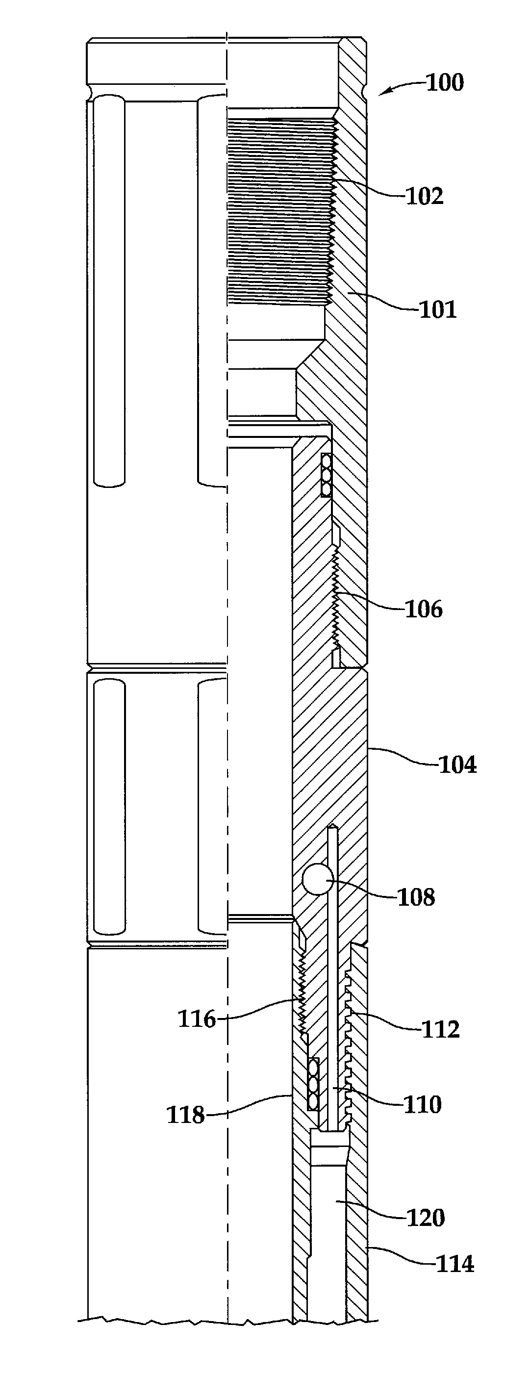
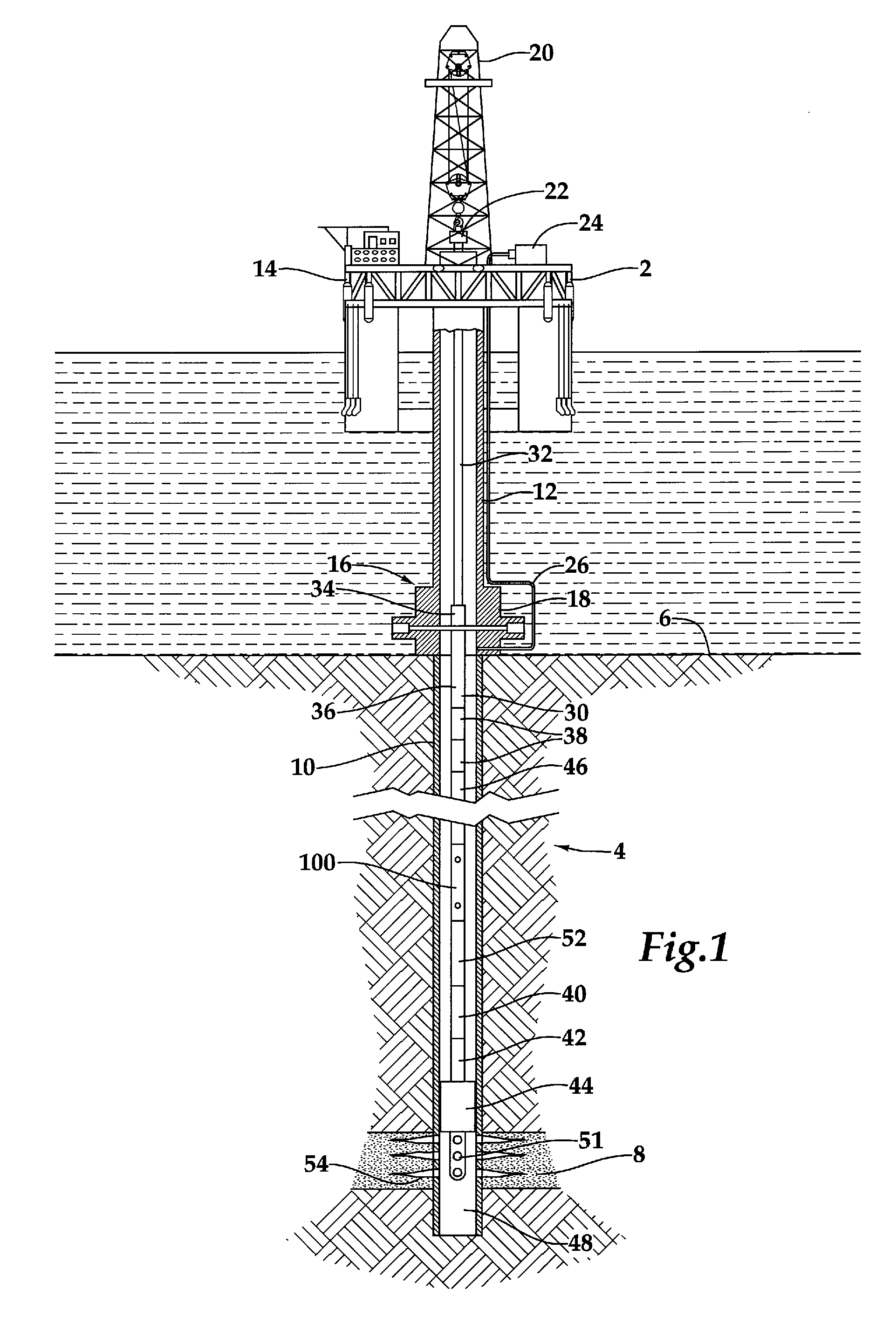
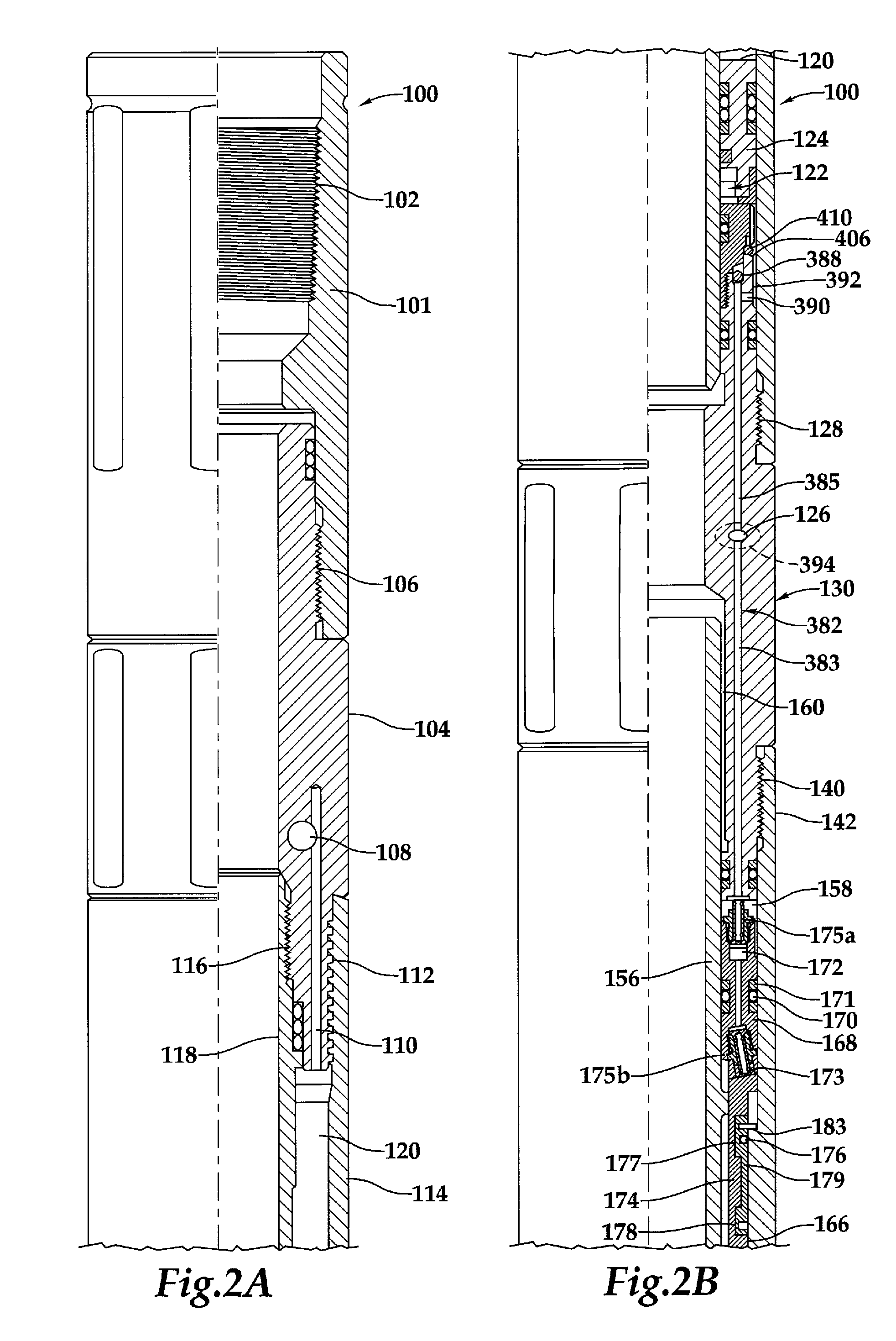
[0024]Referring now to the drawings in more detail, and particularly to FIG. 1, therein is depicted an exemplary multi-mode testing tool 100 operable in accordance with the methods and apparatus of the present invention, in an exemplary operating environment, disposed adjacent a potential producing formation in an offshore location. In the depicted exemplary operating environment, an offshore platform 2 is shown positioned over submerged oil or gas wellbore 4 located in the sea floor 6, with wellbore 4 penetrating a potential producing formation 8. Wellbore 4 ...


PUM


Abstract

Well tools are provided which although pressure responsive, may be maintained by a hydraulic lockout in a nonresponsive condition until a threshold actuation step is performed. This lockout may be achieved by a hydraulic mechanism which controls the rate at which pressure is transmitted to a fluid spring during periods of increased pressure at the pressure source. When the tool is desired to be responsive to pressure cycles, a valve may be opened by established a differential between the pressure in the fluid spring and the pressure source. Communication of pressure in the fluid spring to a movable mandrel will then allow operation of the well tool in response to pressure cycles at the pressure source in accordance with the established design of the well tool.

Description

FIELD OF THE INVENTION[0001]This invention relates, in general, to pressure controlled well tools and, in particular, to methods and apparatuses for selectively locking out or preventing operation of selected pressure controlled well tools until such time as operation is desired.BACKGROUND OF THE INVENTION[0002]Without limiting the scope of the present invention, its background is described with reference to pressure controlled well tools, as an example.[0003]It is well known in the subterranean well drilling and formation testing arts that many types of well tools are responsive to pressure, either in the annulus or in the tool string. For example, different types of tools for performing drill stem testing operations are responsive to either tubing or annulus pressure, or to a differential therebetween. Additionally, other tools such as safety valves or drill string drain valves may be responsive to such a pressure differential.[0004]Such well tools typically have some member, such...

Claims


Application Information

Patent Timeline
IPC IPC(8): E21B34/10E21B34/06E21B23/00
CPCE21B23/006E21B34/063E21B2034/002E21B34/108E21B34/102E21B2200/04
Inventor RINGGENBERG, PAUL D.NIVENS, HAROLD W.
Owner HALLIBURTON ENERGY SERVICES INC
Why Eureka
Try Eureka