Lighted nock for archery arrow

a technology of archery arrows and nocks, which is applied in the field of archery arrows, can solve the problems of unplanned light shutting off, huge disappointment, and light shutting o

Active Publication Date: 2010-11-23
HUANG RICHARD +1
View PDF7 Cites 90 Cited by
  • Summary
  • Abstract
  • Description
  • Claims
  • Application Information

AI Technical Summary

Benefits of technology

[0011]The arrow of this invention may be shot with a bow, in which the bow may desirably define an arrow rest structure attached to the bow and projecting laterally outwardly therefrom. The arrow rest structure may carry a magnet for activating the light assembly as an arrow is shot with the bow. Because the magnet is carried on the arrow rest structure and not the bow itself, the magnet may be placed closer to the arrow, so that the magnet may be momentarily closer than ½ inch to the light assembly as the arrow is shot from the bow. Thus, a momentarily stronger magnetic field may be imposed on the light assembly by this means, permitting use of a less sensitive magnetic switch. An advantage of this is that the light assembly is less likely to accidentally turn on through jostling or dropping of an arrow, while it still may be reliably turned on when fired by such a bow. However, the invention of this application may also be used with conventional bows having a conventionally-placed magnet.
[0012]In some embodiments, the light source may comprise a focused beam LED, of a commercially available type, under circumstances in which at least 90% of the light extends rearwardly at no more than a 40° angle from the axis of the arrow. This may be facilitated when the light source is in physical contact with a transparent, inner end wall of the nock, to minimize side scattering of light, rather than utilizing a spaced, air filled chamber between the light source and an inner end wall of a nock.
[0014]Preferably, the first wire loop also defines an overhand knot, which is like the simple first knot of a conventional shoelace tie, comprising a twist of the wires one or more times. The effect of this overhand knot, in the vicinity of and preferably occupying the battery groove, is to greatly increase the ability of the system to retain the battery in connected relation with the nock and light assembly, even under conditions of very high G force, for example when an arrow strikes bone in a quarry, and even when the arrow hits a rock or cement. The first loop occupying the groove helps to provide this significant improvement.
[0015]Also, the wire may define a second loop that extends around the battery, and provides further protection from G forces, particularly lateral force. In addition, an O ring may be placed around the battery to center and cushion it in the bore of the arrow itself, with the O ring being preferably large enough to sealingly engage both the battery and the inner wall of the arrow bore. The O ring may be thick for shock absorbing or thinner, like a rubber band.
[0018]The circuitry used may comprises an analog design with digital components, using fuzzy logic. It avoids the problem of the prior art digital circuit, which loses its accuracy in the cold. One of the functions of the circuit is to hold the light in illuminated condition for a predetermined length of time, irrespective of the shock forces and the like that are encountered. Then, if desired, the circuit can be programmed to shut the light off.

Problems solved by technology

However, when the illuminated arrow strikes a target, it exhibits strong deceleration forces, which, in prior art systems, can cause the light to shut off in unplanned manner.
This can be a huge disappointment to a sport hunter, who has invested heavily both financially and in time for the moment of arrow impact, and then the arrow light shuts off in unplanned manner.
A sport hunter may actually be videotaping the process, and this can be hugely disappointing.
This light can be seen from the front, and may cause the quarry to start, resulting in a miss.

Method used


Image

  • Lighted nock for archery arrow
  • Lighted nock for archery arrow
  • Lighted nock for archery arrow

Examples


Embodiment Construction

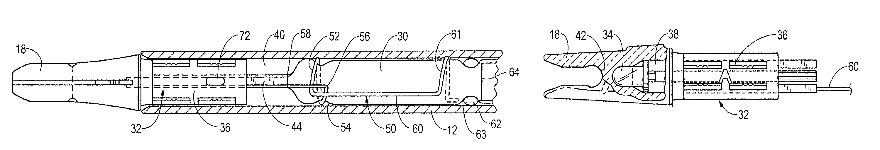
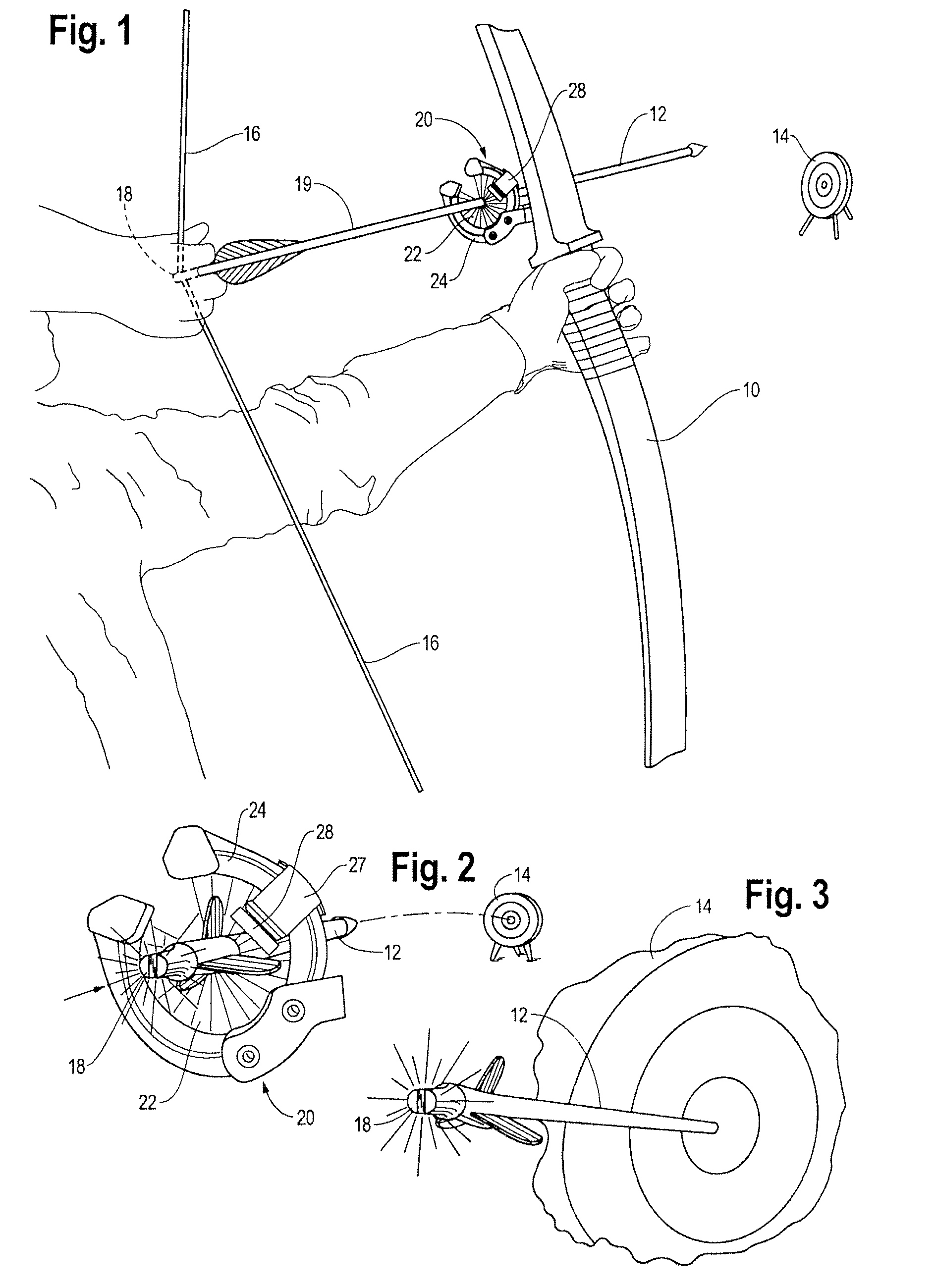
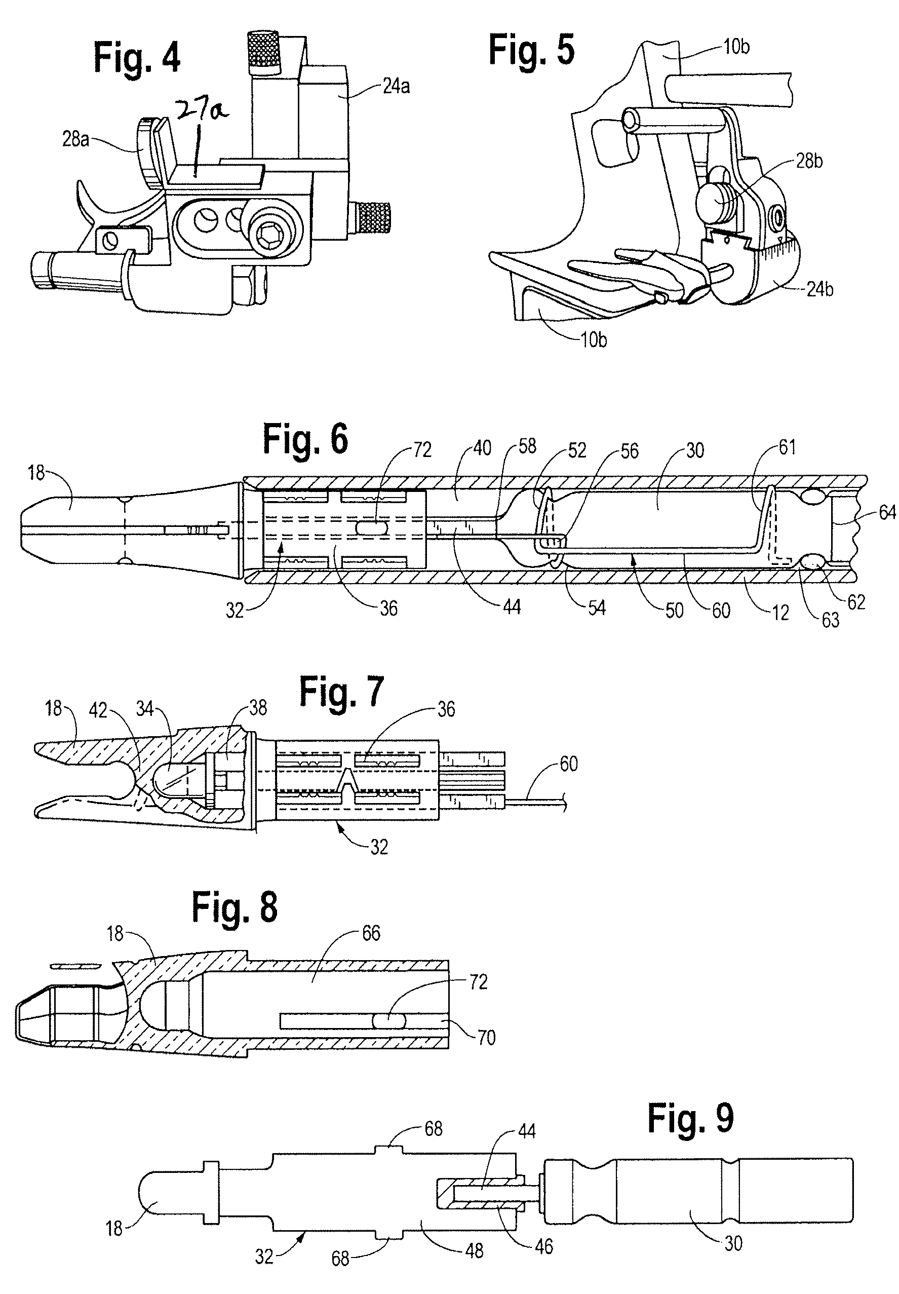
[0007]By this invention, an archery arrow is provided which comprises: a shaft having forward and rearward portions, and having a rearwardly positioned tubular portion; a light transmitting nock attached to the rearward end of the shaft; a battery, which is typically carried in a hollow bore within the shaft; and a light assembly.

[0008]The light assembly, in turn, comprises: a light source positioned so that the light source is visible through the nock; a switch having normally open electrical contacts, the switch being closable upon momentary contact with a magnetic field; and circuitry interconnecting the battery, the switch, and the light source, for permitting illumination of the light source upon momentary sensing of the magnetic field.

[0009]In some embodiments, the light assembly of this invention may be free of the housing, and may occupy a first bore of the nock as well as a second bore of the arrow shaft rearward end.

[0010]The light transmitting nock may advantageously be p...


PUM


Abstract

An archery arrow carries a light transmitting nock plus a light assembly, which comprises a light source positioned so that the light source is visible through the nock, a switch having normally open electrical contacts, and closable upon momentary contact with a magnetic field, and circuitry interconnecting a battery, the switch, and the light source for permitting illumination of the light source when the magnetic field is sensed. By this invention, the light assembly may be free of a housing and occupies a first bore of the nock and a second bore of the arrow shaft rearward end. A unique system for retaining a battery and protecting against high G force, plus a focused beam LED are other optional, advantageous features.

Description

BACKGROUND OF THE INVENTION[0001]In Simonton et al. U.S. Pat. No. 6,390,642 B1, an archery arrow is disclosed in which a magnetically actuated rear light is illuminated, as the arrow is fired from the bow.[0002]Deer hunting, and other forms of hunting, can be a sport to which many are deeply dedicated. The rearwardly pointing light on the end of an arrow can show the hunter the path of the arrow and the place where it hits, whether it be the quarry, or another location. However, when the illuminated arrow strikes a target, it exhibits strong deceleration forces, which, in prior art systems, can cause the light to shut off in unplanned manner. This can be a huge disappointment to a sport hunter, who has invested heavily both financially and in time for the moment of arrow impact, and then the arrow light shuts off in unplanned manner. A sport hunter may actually be videotaping the process, and this can be hugely disappointing. When the arrow continues to emit light after having struc...

Claims


Application Information

Patent Timeline
Patent Type & Authority Patents(United States)
IPC IPC(8): F42B6/04
CPCF42B6/06F42B12/362F42B12/38F42B12/382
Inventor HUANG, RICHARDHUANG, DORGE O'SOME
Owner HUANG RICHARD
Why Eureka
Try Eureka