Method and system of hybrid power management

a hybrid power management and power management technology, applied in secondary cell servicing/maintenance, electrochemical generators, pulse techniques, etc., can solve the problems of fuel cell failure, unstable transient state, and restricted power supply process of fuel cells, so as to prevent the output voltage of fuel cells from dropping, prolong the lifetime of fuel cells, and keep the load operating normally

Inactive Publication Date: 2010-11-23
INST NUCLEAR ENERGY RES ROCAEC
View PDF5 Cites 20 Cited by
  • Summary
  • Abstract
  • Description
  • Claims
  • Application Information

AI Technical Summary

Benefits of technology

[0008]It is an object of the present invention to provide to a method of hybrid power management and a system of hybrid power management, in which one of different output power modes is selected to supply power to the load according to the power state of fuel cell module so as to prevent the output voltage of the fuel cell from dropping due to unstable transient state. Therefore, the fuel cell module can be recovered at unstable transient state to prolong the lifetime of the fuel cell and keep the load operating normally.

Problems solved by technology

However, the power supply process of the fuel cell is restricted to the reaction mechanism therein.
For example, it is hard for the fuel cell to provide large power to the load due to slow oxidation and fuel delivery, which leads to failure of the fuel cell because of insufficient momentary power supply.
Moreover, the unstable transient state occurs due to reduced fuel concentration during fuel supply.
During the operations of the secondary cell, the operation of the secondary cell is insufficient to cause lowered output power when it is over-loaded or has operated overtime.
Meanwhile, aging of the over-used fuel cell results from high current and low voltage because there is no mechanism in the secondary cell module to avoid reduced output power.

Method used


Image

  • Method and system of hybrid power management
  • Method and system of hybrid power management
  • Method and system of hybrid power management

Examples


Embodiment Construction

[0021]The present invention can be exemplified but not limited by the preferred embodiments as described hereinafter.

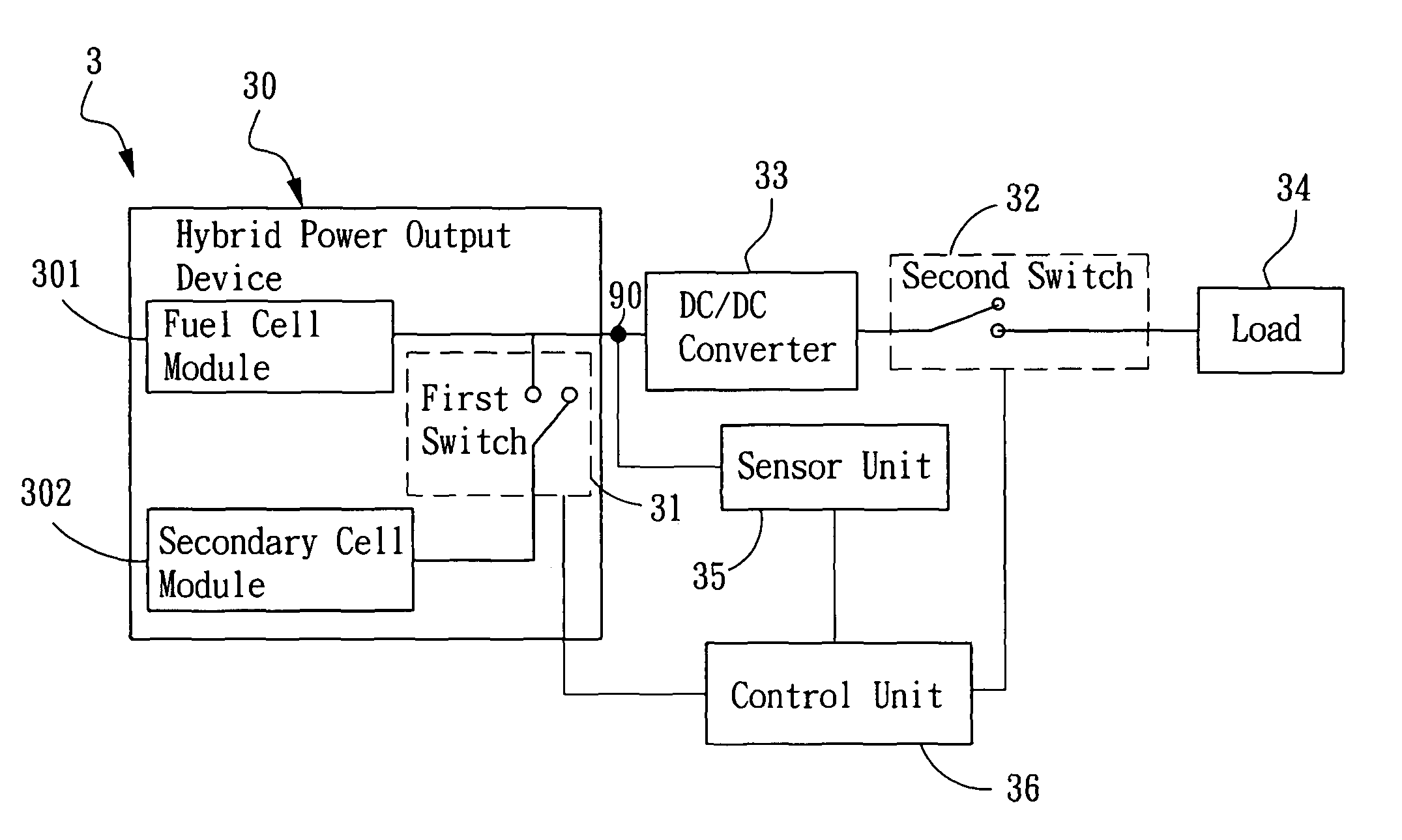
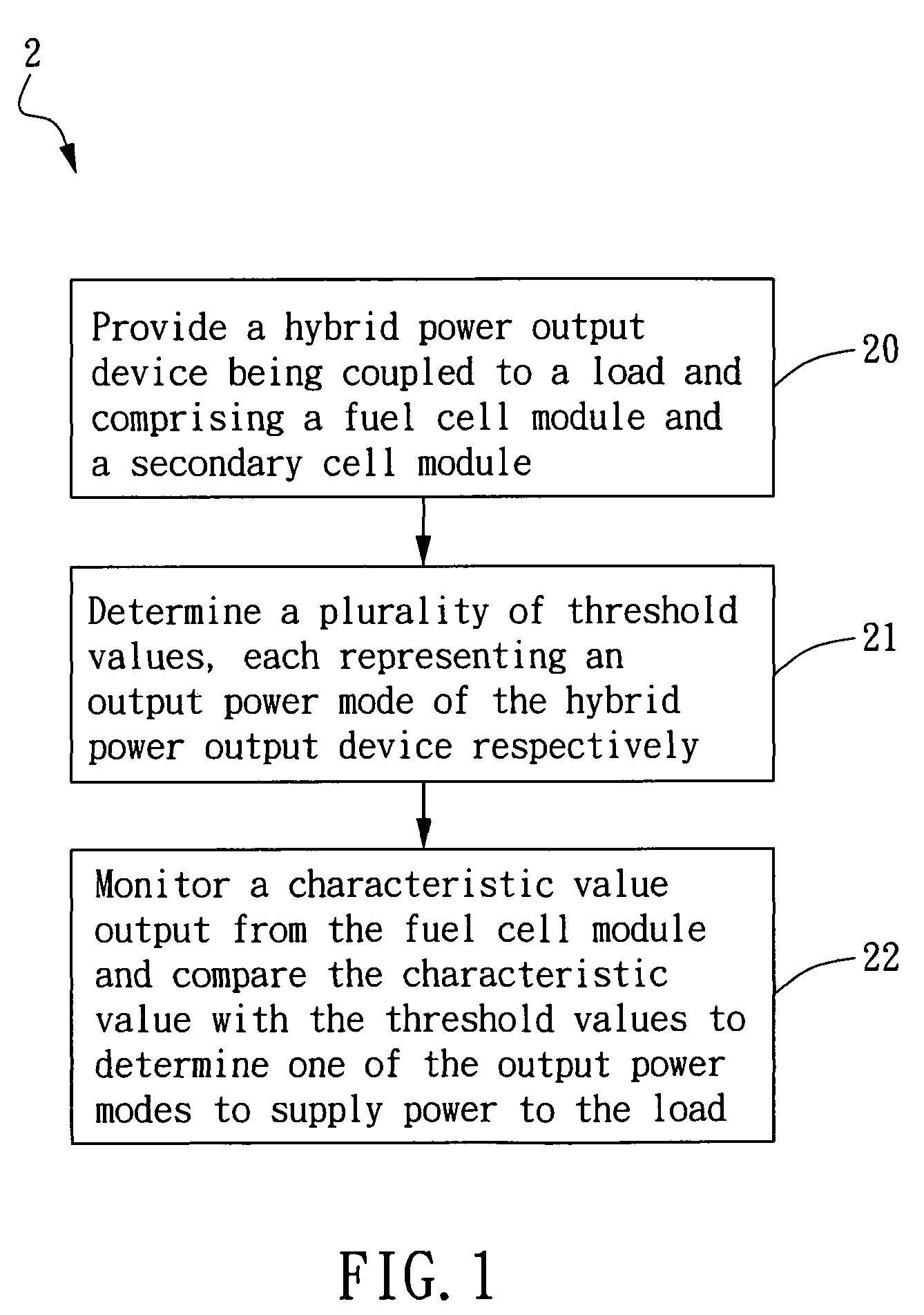
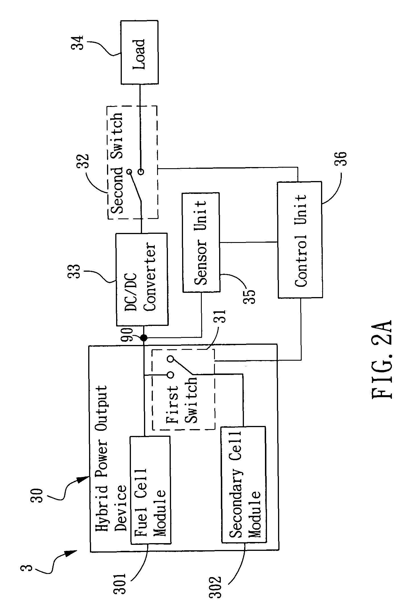
[0022]Please refer to FIG. 1, which is a flowchart of a method of hybrid power management according to the present invention. The method of hybrid power management 2 comprises steps described hereinafter. First, Step 20 is performed to provide a hybrid power output device. The hybrid power output device is coupled to a load and comprises a fuel cell module and a secondary cell module. The fuel cell module can be a direct methanol fuel cell (DMFC) or a solid oxide fuel cell (SOFC), but not restricted thereto. The secondary cell can be a lithium cell, nickel-metal hydride (NiMH) cell or any other rechargeable cell.

[0023]Then, in Step 21, a plurality of threshold values are determined. Each threshold value represents an output power mode of the hybrid power output device respectively. The output power mode in this step represents the power simply from the fuel cell modul...


PUM


Abstract

A method of hybrid power management is provided in the present invention, comprising steps of: providing a hybrid power output device being coupled to a load and comprising a fuel cell module and a secondary cell module; determining a plurality of threshold values, each representing one of output power modes of the hybrid power output device respectively; and monitoring a characteristic value output from the fuel cell module and comparing the characteristic value with the threshold values to determine one of the output power modes to supply power to the load. Moreover, the present invention further provides a system of hybrid power management using the foregoing method to control switches to select from the output power modes such as supplying power from the fuel cell module only, from both the fuel cell module and the secondary battery, or cutting off power supply to the load according to the power state of the fuel cell module.

Description

BACKGROUND OF THE INVENTION[0001]1. Field of the Invention[0002]The present invention generally relates to a power control method and a power control system using the same and, more particularly, to a method of hybrid power management and a system of hybrid power management, in which one of different output power modes is selected according to a characteristic value output from a fuel cell module.[0003]2. Description of the Prior Art[0004]The fuel cell has attracted tremendous attention as an alternative energy because it is free of pollution, high-efficiency, low-noise, low-vibration, fast start-up and long duration. Especially, the awakening in environmental conscience has made the fuel cell a potential power source for use in other fields. The fuel cell has advanced so that the power generation performance is improved with reduced material cost is to make the fuel cell commercialized.[0005]However, the power supply process of the fuel cell is restricted to the reaction mechanism ...

Claims


Application Information

Patent Timeline
Patent Type & Authority Patents(United States)
IPC IPC(8): H02J1/00H02J7/34
CPCH01M8/04537H01M8/04559H01M8/04567H01M8/0494H01M8/04947H01M8/04955H01M16/006H02J7/34H01M8/04589H01M8/04597H02J2001/004Y02E60/50H02J2300/30Y02E60/10
Inventor CHEN, CHARN-YINGCHANG, CHI-YUANLIN, WEI-WEIHUANG, CHIH-LINLIN, YEONG-DER
Owner INST NUCLEAR ENERGY RES ROCAEC
Why Eureka
Try Eureka