
Method of driving a lamp, lamp driving apparatus, and liquid crystal display device having the same

a technology of liquid crystal display device and lamp, which is applied in the direction of lighting apparatus, instruments, light sources, etc., can solve the problems of difficult implementation of moving image technology in the lcd device, and achieve the effect of removing the motion blur of a moving image and not affecting the life and characteristics of the lamp

Inactive Publication Date: 2010-11-23
SAMSUNG DISPLAY CO LTD
View PDF2 Cites 5 Cited by
  • Summary
  • Abstract
  • Description
  • Claims
  • Application Information

AI Technical Summary

Benefits of technology

The present invention provides a method and apparatus for driving a lamp that can remove motion blur of a moving image by adjusting the driving duty cycle of the lamp and the supplied power. This is done by calculating the change rate of the image and adjusting the driving signals accordingly. The method and apparatus can be used in a liquid crystal display device, which includes a panel section, a lamp section, an image signal processing section, and a lamp driving section. The method and apparatus can adjust the emission duty cycle of the lamp and the current supplied to the lamp, while maintaining the overall power supply to the panel. The invention allows for the removal of motion blur without adversely affecting the life and characteristics of the lamp.

Problems solved by technology

The technology for displaying moving images, however, is somewhat difficult to implement in the LCD device, because a response speed of the liquid crystal is slower than a one-frame period, that is, a time period corresponding to one frame, when a new voltage is supplied to the liquid crystal at the following frame after maintaining a voltage, for example, an image signal or a data voltage, charged in the liquid crystal during the one frame period, motion blur is generated.

Method used


Image

  • Method of driving a lamp, lamp driving apparatus, and liquid crystal display device having the same
  • Method of driving a lamp, lamp driving apparatus, and liquid crystal display device having the same
  • Method of driving a lamp, lamp driving apparatus, and liquid crystal display device having the same

Examples


Embodiment Construction

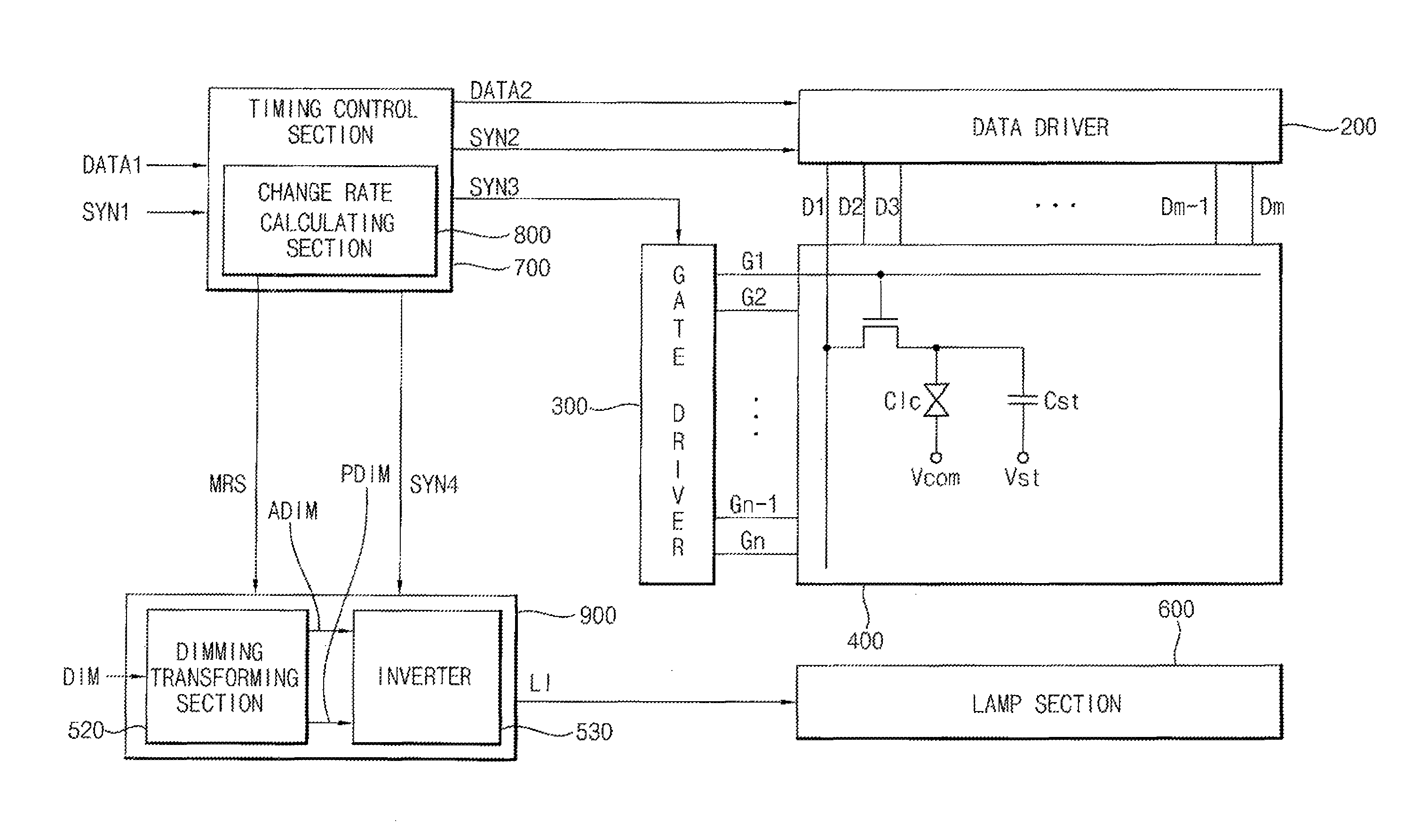
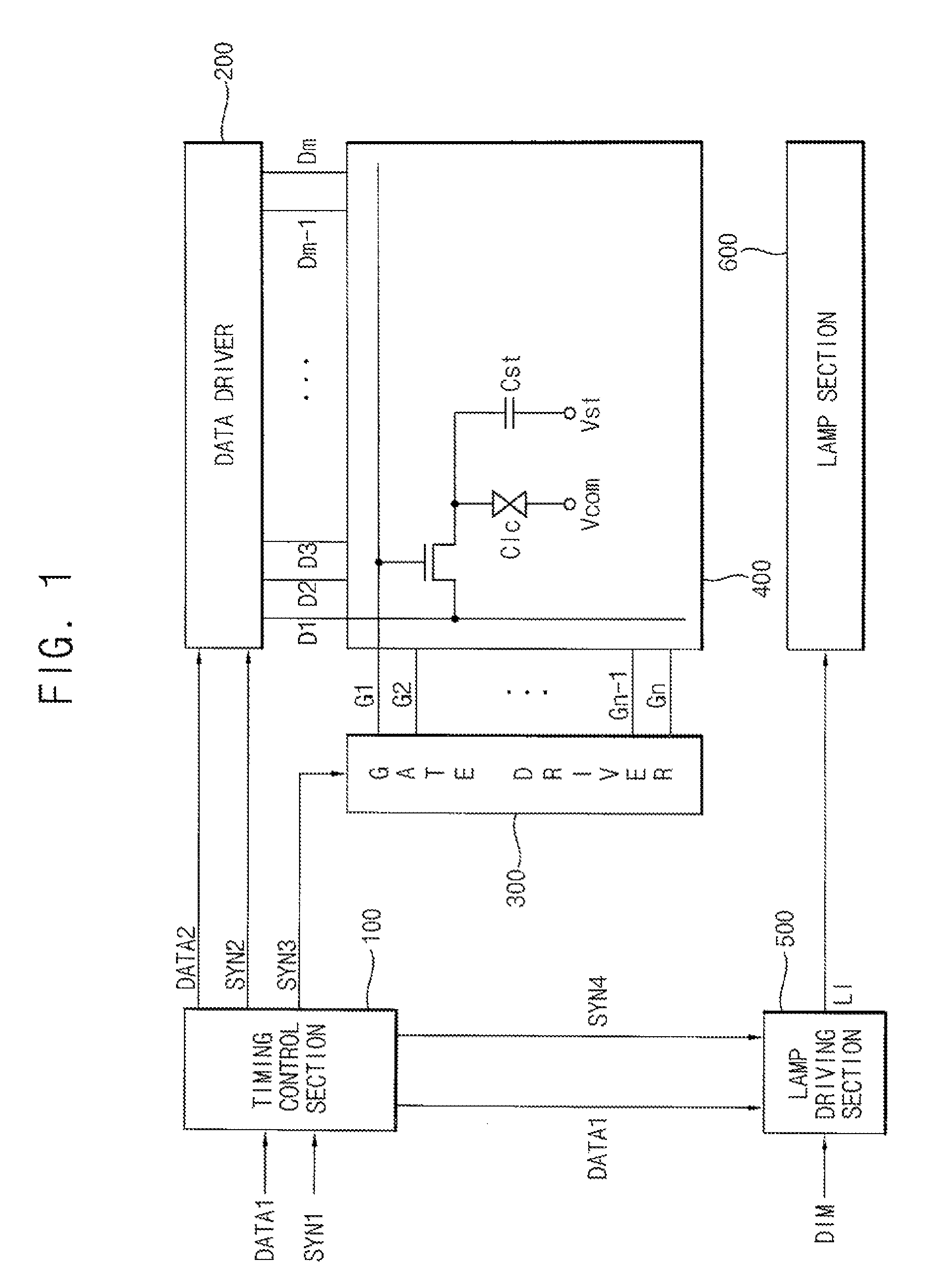
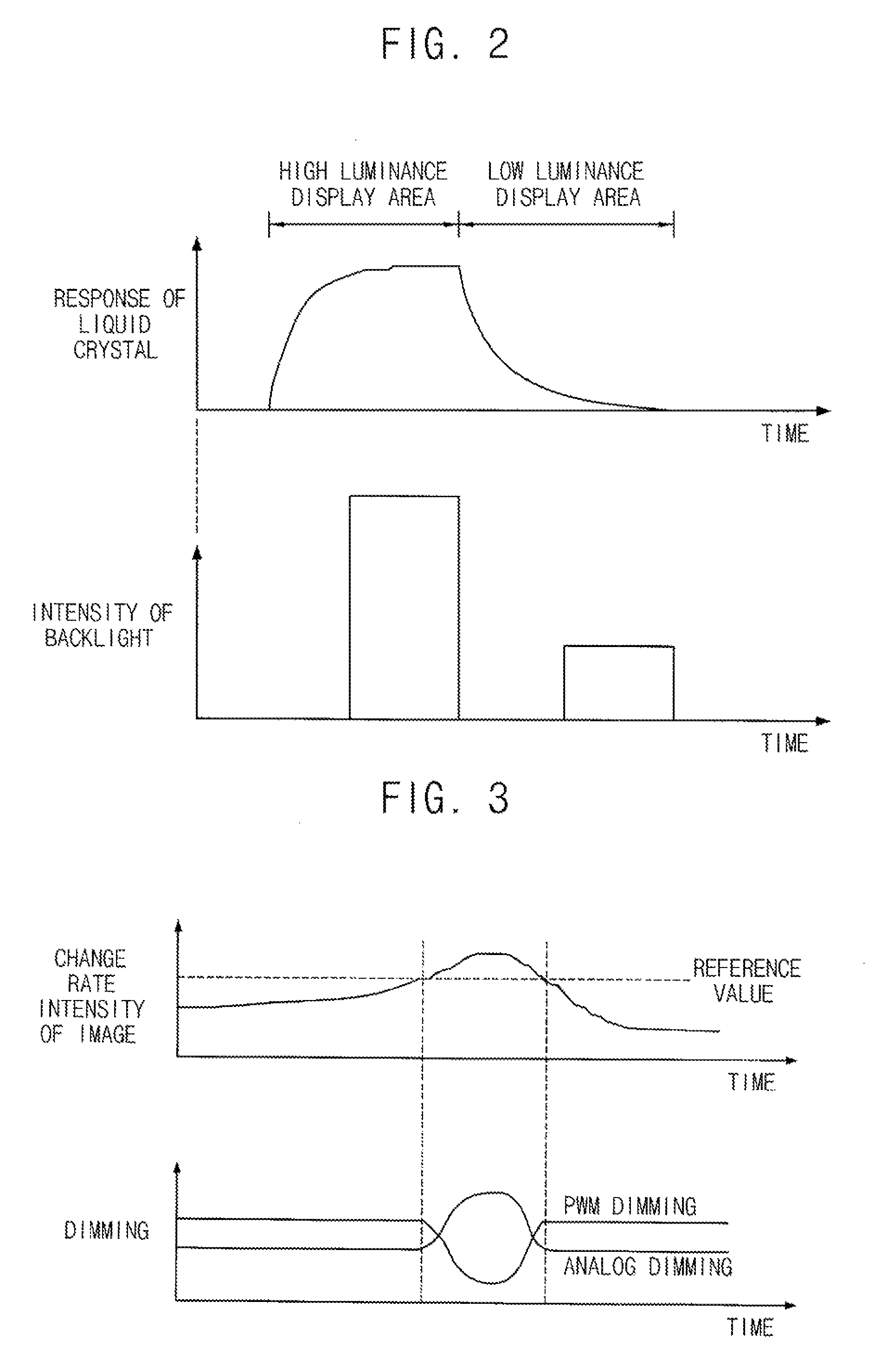
[0037]FIG. 1 is a block diagram illustrating a liquid crystal display (“LCD”) device according to an exemplary embodiment of the present invention. FIG. 2 illustrates graphs showing an intensity of a backlight according to a displayed image.

[0038]Referring to FIG. 1, an LCD device according to an exemplary embodiment of the present invention includes a timing control section 100, a data driver 200, a gate driver 300, an LCD panel 400, a lamp driving section 500 and a lamp section 600. The timing control section 100, a data driver 200 and a gate driver 300 may define an image signal processing section that provides the LCD panel 400 with an image signal for display that is applied from an external device.

[0039]The timing control section 100 receives a first image signal DATA1 and a first synchronizing signal SYN1, and outputs a second image signal DATA2, a second synchronizing signal SYN2 and a third synchronizing signal SYN3. The first synchronizing signal SYN1 includes a vertical s...


PUM


Abstract

A lamp driving apparatus includes a change rate calculating section, a dimming transforming section and a power supplying section. The change rate calculating section calculates a change rate signal from an image signal corresponding to the image. The dimming transforming section outputs a digital dimming signal and an analog dimming signal, in response to a dimming signal provided from an external device and the change rate signal. The power supplying section provides the lamp with power, in response to a vertical synchronizing signal, the analog dimming signal and the digital dimming signal. Thus, although an instantaneous lamp current is increased, life and characteristics of the lamp will not be adversely influenced, and motion blur of a moving image may be removed.

Description

CROSS-REFERENCE TO RELATED APPLICATION[0001]This application claims priority from Korean Patent Application No. 2006-11052 filed on Feb. 6, 2006 in the Korean Intellectual Property Office, The contents of which are herein incorporated by reference in their entirety.BACKGROUND OF THE INVENTION[0002]1. Technical Field[0003]The present disclosure relates to a method of driving a lamp, a lamp driving apparatus for performing the method of driving the lamp, and a liquid crystal display device having the lamp driving apparatus. More particularly, the present disclosure relates to a method of driving a lamp for variably adjusting a driving duty cycle of the lamp and adjusting a supply voltage according to an image change rate, a lamp driving apparatus for performing the method of driving the lamp, and a liquid crystal display device having the lamp driving apparatus.[0004]2. Discussion of the Related Art[0005]Generally, a liquid crystal display (“LCD”) device displays an image thereon by a...

Claims


Application Information

Patent Timeline
Patent Type & Authority Patents(United States)
IPC IPC(8): H05B37/00
CPCG09G3/3406H05B41/3927G09G2320/0633G09G2320/064G09G2320/103G09G2360/18G02F1/1335H05B41/38
Inventor KIM, MIN-GYUJANG, HYEON-YONG
Owner SAMSUNG DISPLAY CO LTD
Learn More