Optical fiber illumination device and inspection apparatus

a technology of optical fiber and illumination device, which is applied in the direction of instruments, holographic light sources/light beam properties, holographic processes, etc., can solve the problems of affecting the results of inspection, requiring a lot of time to collect information, and preventing the medium from being inspected, so as to achieve stable intensity, stably detect authenticity, and spread light

Active Publication Date: 2010-11-23
KK TOSHIBA
View PDF14 Cites 6 Cited by
  • Summary
  • Abstract
  • Description
  • Claims
  • Application Information

AI Technical Summary

Benefits of technology

[0012]The present invention has been contrived in consideration of the above-described circumstances, and its object is to provide an optical fiber illumination apparatus which can illuminate a region to be inspected with stably spreading light and at a stable intensity, as well as an inspection apparatus which can stably detect the authenticity and damage of a hologram-attached medium to be inspected.
[0014]With the above-described structure, it is possible to provide an inspection apparatus which can detect the authenticity and deficiency of a hologram-attached paper instrument in a stable manner.

Problems solved by technology

However, the conventional inspection apparatus of the type which utilizes laser light entails such drawbacks as that the conditions for stopping the medium to be inspected for observation are severe, and it requires much time to collect information and for identification process.
The conventional inspection apparatus designed to inspect a moving medium entails such a drawback that the rattling of the medium to be inspected causes an adverse effect to the results of the inspection.
Further, paper instruments such as of securities, as they are circulated, will wear down so that the surface condition thereof deteriorates due to chipping, peeling-off, cut, wrinkle, etc., and accordingly there is a possible that the basic optical characteristics of the hologram are lost, which is called “fatigue”.
However, there has been no such apparatus provided to inspect such damage, fatigue, etc. of the hologram.
As a result, the spreading of the light and the light intensity within the view field to be detected is uneven.
A hologram inspection apparatus that uses such an illumination is not able to stably obtain the data within the entire view field to be inspected, which causes an adverse effect on the inspection accuracy.

Method used


Image

  • Optical fiber illumination device and inspection apparatus
  • Optical fiber illumination device and inspection apparatus
  • Optical fiber illumination device and inspection apparatus

Examples


first embodiment

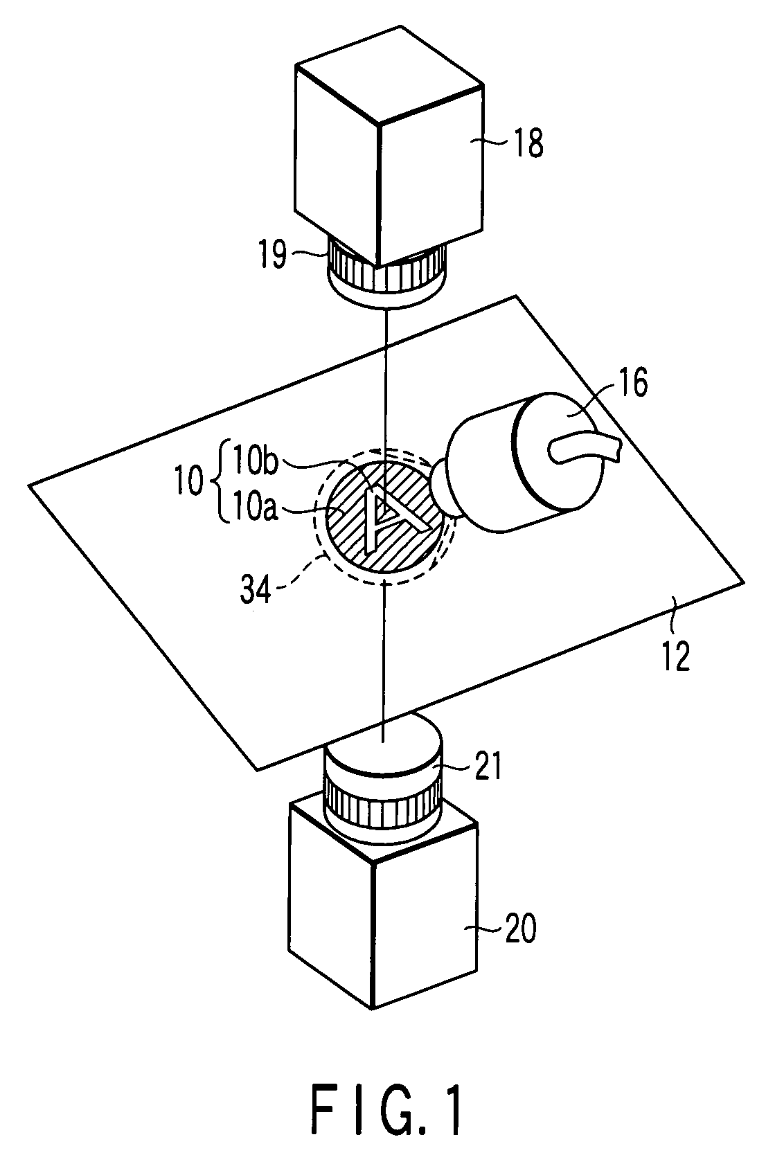
[0042]As shown in FIGS. 1 and 2, a paper instrument inspection apparatus includes a holder mechanism 14 which holds a paper instrument 12 such as a valuable paper certificate to which a hologram 10 to be inspected is attached, a light source unit 16 which irradiates illumination light for inspection on the paper instrument, a first light receiving sensor 18 which receives reflection light from the hologram 10 and a second light receiving sensor 20 which receives transmitted light passed through the paper instrument.

[0043]The hologram 10 includes, for example, a round-shaped metal foil 10a attached onto the paper instrument 12 and a diffraction pattern (diffraction grating) 10b of a desired shape, for example, in this embodiment a shape of letter “A” formed on the metal foil. The hologram 10, when visible light is irradiated thereon at a predetermined angle, reflects diffraction light corresponding to the diffraction pattern 10b, and shows a rainbow-color characteristic pattern.

[004...

second embodiment

[0060]Next, the present invention will now be described.

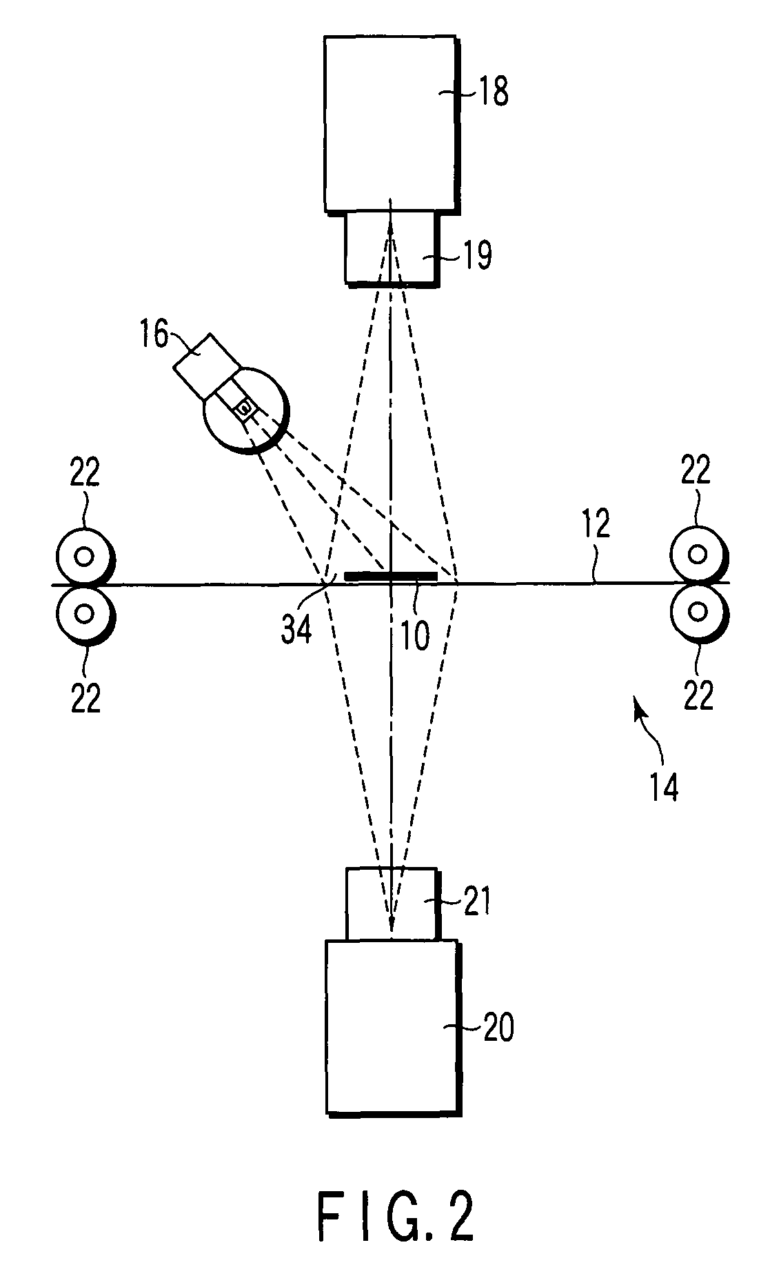
[0061]In the first embodiment described above, the hologram is inspected while the paper instrument 12 is set still. On the other hand, according to the second embodiment, the inspection apparatus includes a conveying mechanism 15 which conveys the paper instrument 12 along a direction C which is in parallel with the paper surface while applying a tension to the paper instrument along the plane direction of the paper instrument. The conveying mechanism 15 includes a plurality of conveying rollers 40 which convey the paper instrument while holding it between the respective rollers and a conveying belt which is not shown in the figure.

[0062]According to the inspection apparatus, illumination light is irradiated from the light source unit 16 onto the illumination area 34 including the hologram 10 while conveying the paper instrument 12 by the conveying mechanism 15. The reflection light from the hologram is detected by the first l...

third embodiment

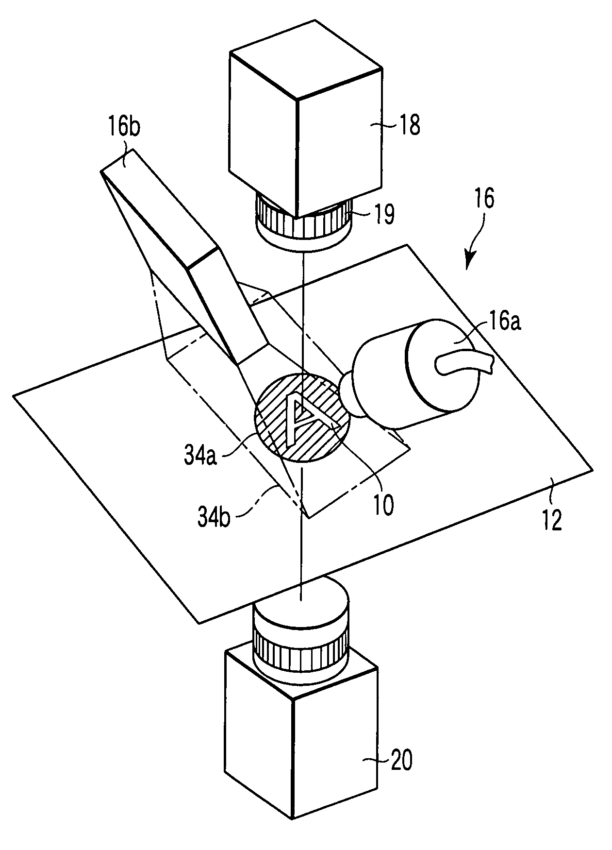
[0064]Next, a third embodiment will now be described.

[0065]As shown in FIGS. 7 and 8, according to the third embodiment, the paper instrument inspection apparatus includes tow illumination units as the light source unit 16. More specifically, the light source unit 16 includes a spotlight device 16a and a transmitting illumination light device 16b which irradiates illumination light to transmit the paper instrument.

[0066]The spotlight device 16a irradiates spotlight illumination onto an illumination area 34a in which a hologram 10 is provided. The spotlight device 16a is formed as a light source which irradiates illumination light of the visible light range. The spotlight device 16a is set at a predetermined angle with respect to the paper instrument 12 and it irradiates onto the hologram illumination light having an optimized directivity to be able to obtain a diffraction image by the diffraction pattern 10b of the object hologram 10.

[0067]The transmitting illumination light device ...


PUM


Abstract

An inspection apparatus includes a light source unit which irradiates illumination light onto a hologram of a medium from a predetermined direction at which diffraction light from the hologram is obtained, a first light receiving member which receives the diffraction light from the hologram, a second light receiving member which receives transmitted part of illumination light irradiated onto the hologram, having passed through the medium, and an identification processing unit which identifies authenticity of the hologram from the diffraction light received by the first light receiving member and identifies a defect of the hologram from the transmitted light received by the second light receiving member.

Description

CROSS-REFERENCE TO RELATED APPLICATIONS[0001]This application is based upon and claims the benefit of priority from prior Japanese Patent Applications No. 2006-062760, filed Mar. 8, 2006; and No. 2007-044138, filed Feb. 23, 2007, the entire contents of both of which are incorporated herein by reference.BACKGROUND OF THE INVENTION[0002]1. Field of the Invention[0003]The present invention relates to an optical fiber illumination device which irradiates illumination light onto a medium to be inspected, such as a card, and an inspection apparatus which inspects a medium to be inspected, such as a hologram-attached paper instrument.[0004]2. Description of the Related Art[0005]A diffraction optical variable device (to be referred to as optical OVD), a typical example of which is a hologram, is a device processed to induce the light diffraction phenomenon on the surface thereof, and it has a pattern which generates vivid colors due to optical diffraction and interference caused by the diff...

Claims


Application Information

Patent Timeline
Patent Type & Authority Patents(United States)
IPC IPC(8): G03H1/00
CPCG03H1/2286G07D7/0013G07D7/121G03H1/0011G03H2001/2231G03H2001/2247G03H2222/34G07D7/0032G03H1/02G01N21/892G01B11/30G02B6/00
Inventor MIURA, JUNJINAKANO, TAKAHISA
Owner KK TOSHIBA
Why Eureka
Try Eureka